Table of Contents
Advertisement
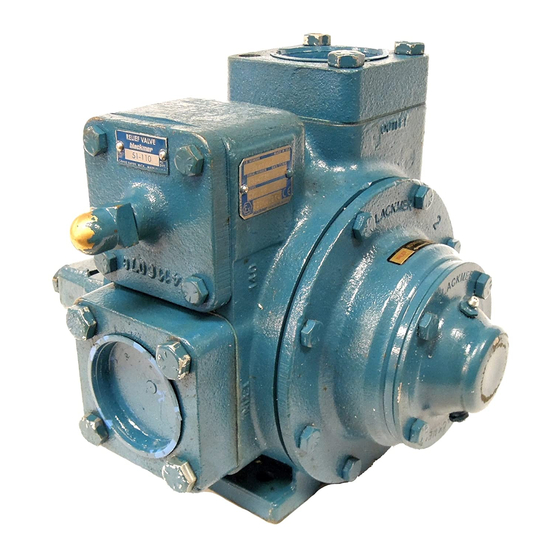
BLACKMER TRUCK PUMPS
INSTALLATION OPERATION AND MAINTENANCE INSTRUCTIONS
and Discontinued TXV2(A)(B), 2½(A), 3(A) Models
Numbers in parentheses following individual parts
indicate reference numbers on Blackmer Parts Lists
202-A01, 202-A02 and 202-A03.
Blackmer pump manuals and parts lists may be
obtained from Blackmer's website (www.blackmer.com)
or by contacting Blackmer Customer Service.
This is a SAFETY ALERT SYMBOL.
When you see this symbol on the product, or in the
manual, look for one of the following signal words and be
alert to the potential for personal injury, death or major
property damage
Warns of hazards that WILL cause serious personal injury,
death or major property damage.
Warns of hazards that CAN cause serious personal injury,
death or major property damage.
Warns of hazards that CAN cause personal injury
or property damage.
NOTICE:
Indicates special instructions which are very
important and must be followed.
MODELS: TXV2.5B, 3B
SAFETY DATA
TABLE OF CONTENTS
Technical Data ....................................................... 2
Initial Pump Start Up Information ........................... 2
Pre-Installation Cleaning ........................................ 3
Location and Piping ............................................... 3
Truck Mounting ...................................................... 3
Pump Drive ............................................................ 3
Pump Rotation ....................................................... 4
To Change Pump Rotation .................................... 4
Pre-Start Up Check List ......................................... 5
Start Up Procedures .............................................. 5
Pump Speed .......................................................... 5
Reverse Rotation ................................................... 5
Flushing the Pump ................................................. 6
Pump Relief Valve ................................................. 6
Relief Valve Setting and Adjustment...................... 6
Strainers ................................................................ 7
Lubrication ............................................................. 7
Vane Replacement ................................................ 8
Pump Disassembly ................................................ 8
Pump Assembly ..................................................... 8
TROUBLE SHOOTING ......................................
NOTICE:
Blackmer Truck Pumps MUST only be installed in systems,
which have been designed by qualified engineering
personnel.
The system MUST conform to all applicable
local and national regulations and safety standards.
This manual is intended to assist in the installation and
operation of the Blackmer truck pumps, and MUST be kept
with the pump.
Pump service shall be performed by qualified technicians
ONLY.
Service shall conform to all applicable local and
national regulations and safety standards.
Thoroughly review this manual, all instructions and hazard
warnings, BEFORE performing any work on the pump.
Maintain ALL system and pump operation and hazard
warning decals.
960296
INSTRUCTIONS NO. 202-A00
Section
202
Effective
Jan 2014
Replaces
July 2007
Page
10
Advertisement
Table of Contents

Subscribe to Our Youtube Channel
Related Manuals for BLACKMER TXV2.5B


Summary of Contents for BLACKMER TXV2.5B
-
Page 1: Table Of Contents
This manual is intended to assist in the installation and operation of the Blackmer truck pumps, and MUST be kept with the pump. Warns of hazards that WILL cause serious personal injury, Pump service shall be performed by qualified technicians death or major property damage. -
Page 2: Pump Data
A pump Identification tag, containing the pump serial number, I.D. number, and model designation, is attached to each pump. It is recommended that the data from this tag be recorded and filed for future reference. If replacement parts are needed, or if information pertaining to the pump is required, this data must be furnished to a Blackmer representative. TECHNICAL DATA INITIAL PUMP START UP INFORMATION Model No.: ___________________________________... -
Page 3: Installation
The pump will operate satisfactorily in any position. Consult 3. Use an even number of universal joints. Blackmer factory for vertical shaft mounts. The pump can be 4. The pump shaft and power take-off shaft must be parallel bolted to the truck frame or on a saddle hung below the in all respects. -
Page 4: Pump Rotation
Confirm correct pump rotation by checking the pump pump shaft in all respects. Blackmer provides an optional rotation arrows respective to pump driver rotation. close-coupled hydraulic motor adapter. The adapter provides for straight alignment of a hydraulic motor drive through a solid coupling connected to a straight key shaft. -
Page 5: Operation
OPERATION START UP PROCEDURES NOTICE: Consult the "General Pump Troubleshooting" section of Pumps operating against a closed this manual if difficulties during start up are experienced. valve can cause system failure, personal injury and property damage 1. Ensure that appropriate valves are open in the inlet and Hazardous pressure discharge lines. -
Page 6: Flushing The Pump
Refer to the individual Blackmer pump parts lists for spring Pumping volatile liquids under suction lift may cause pressure ranges. The pumps are supplied from the factory cavitation. -
Page 7: Maintenance
MAINTENANCE Failure to set the vehicle emergency Disconnecting fluid or pressure brake and chock wheels before containment components during pump performing service can cause severe operation can cause serious personal personal injury or property damage. injury, death or major property damage Hazardous pressure Hazardous pressure can cause personal... -
Page 8: Vane Replacement
MAINTENANCE VANE REPLACEMENT 6. Slide the head off the shaft. The head O-ring (72), bearing (24), and mechanical seal (153) or lip seal (152) will come NOTICE: off with the head. Remove and discard the head O-ring. Maintenance shall be performed by qualified technicians a. - Page 9 MAINTENANCE 3. Install the head (20) on the outboard side of the cylinder. d. Insert the retaining ring (152D) into the groove in the Install and uniformly tighten four head capscrews (21) 90° housing. apart, torquing to 25 lbs. ft (34 Nm). e.
- Page 10 MAINTENANCE 11. Rotate the shaft by hand to engage the mechanical seal 13. Inspect the grease seal (104) for wear or damage and drive tangs (if equipped), and to test for binding or tight replace as required. Grease the outside diameter of the spots.
-
Page 11: Troubleshooting
TROUBLESHOOTING NOTICE: Maintenance shall be performed by qualified technicians only, following the appropriate procedures and warnings as presented in this manual. SYMPTOM PROBABLE CAUSE Pump not wetted. Worn vanes. Suction valve closed. Air leaks in the suction line. Strainer clogged. Pump Not Priming Suction line or valves clogged or too restrictive. - Page 12 Liquefied Gas Transfer, Boosting, Vapor Recovery Hand Operated Pumps Accessories Dispensing, Transfer, In-line Gear Reducers, Bypass Valves, Strainers Visit www.blackmer.com for complete information on all Blackmer products : " " 1528, ." " 3, e .5 : 02/ 973 27 67, e-mail: o ce_bg@opwmarket.com...
Need help?
Do you have a question about the TXV2.5B and is the answer not in the manual?
Questions and answers