Table of Contents
Advertisement
BLACKMER LIQUEFIED GAS PUMPS
FOR LP-GAS AND NH
INSTALLATION OPERATION AND MAINTENANCE INSTRUCTIONS
Patent Protected by U.S. Patent 6030191 and Related Foreign Patents.
TABLE OF CONTENTS
.................................................................. 1
...................................................................... 2
Pump Identification ..................................................... 2
Technical Data ........................................................... 2
Initial Pump Start Up Information ............................... 2
Welded Connections .................................................. 3
Pump Mounting .......................................................... 3
Pre-Installation Cleaning ............................................ 3
Location and Piping .................................................... 3
Auxiliary Inlet .............................................................. 3
Pump Drive ................................................................ 4
Hydraulic Drive ........................................................... 4
Pump Relief Valve and Bypass Valve ........................ 4
Pump Rotation ........................................................... 4
Pre-Start Up Check List ............................................. 5
Start Up Procedures ................................................... 5
Pump Speed .............................................................. 5
..................................................................
Lubrication .................................................................. 6
Vane Replacement ..................................................... 7
Pump Disassembly .................................................... 7
Pump Assembly ......................................................... 8
NOTE: Numbers in parentheses following individual parts
indicate reference numbers on Blackmer Parts List 501-D01
Blackmer pump manuals and parts lists may be obtained from
Blackmer's website (www.blackmer.com) or by contacting
Blackmer Customer Service.
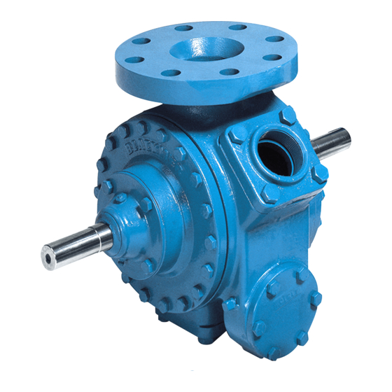
MODEL: TLGLF3C
.................................................. 10
SERVICE
3
When you see this symbol on the product, or in the manual,
look for one of the following signal words and be alert to the
potential for personal injury, death or major property damage
Warns of hazards that WILL cause serious personal injury,
Warns of hazards that CAN cause serious personal injury,
Warns of hazards that CAN cause personal injury
Page
Indicates special instructions which are very
Blackmer liquefied gas pumps MUST only be installed
in systems which have been designed by qualified
engineering personnel. The system MUST conform to
all applicable local and national regulations and safety
standards.
This manual is intended to assist in the installation
and operation of the Blackmer liquefied gas pumps,
and MUST be kept with the pump.
Blackmer liquefied gas pump service shall be
performed by qualified technicians ONLY. Service
shall conform to all applicable local and national
regulations and safety standards.
Thoroughly review this manual, all Instructions and
hazard warnings, BEFORE performing any work on
the Blackmer liquefied gas pumps.
Maintain ALL system and Blackmer liquefied gas
pump operation and hazard warning decals.
960425
INSTRUCTIONS NO. 501-D00
Section
Effective
Replaces
SAFETY DATA
This is a SAFETY ALERT SYMBOL.
death or major property damage.
death or major property damage.
or property damage.
NOTICE:
important and must be followed.
NOTICE:
501
Jan 2014
Aug 2010
Advertisement
Table of Contents

Related Manuals for BLACKMER TLGLF3C


Summary of Contents for BLACKMER TLGLF3C
-
Page 1: Table Of Contents
Blackmer Parts List 501-D01 Maintain ALL system and Blackmer liquefied gas pump operation and hazard warning decals. Blackmer pump manuals and parts lists may be obtained from Blackmer's website (www.blackmer.com) or by contacting Blackmer Customer Service. -
Page 2: Pump Data
A pump Identification tag, containing the pump serial number, I.D. number, and model designation, is attached to each pump. It is recommended that the data from this tag be recorded and filed for future reference. If replacement parts are needed, or if information pertaining to the pump is required, this data must be furnished to a Blackmer representative. TECHNICAL DATA... -
Page 3: Installation
After the welding is complete, reinstall the O-rings. PUMP MOUNTING TLGLF3C pumps are designed to flange mount directly to a commercial internal control valve in combination with the tank of a bobtail truck or transport. Figure 2 5. -
Page 4: Pump Drive
Hydraulic motors should be well supported with their shafts joint, properly lubricated, must be used on the connecting jack parallel to the pump shaft in all respects. Blackmer provides shaft to prevent end thrust on the pump shaft. It is very an optional close-coupled hydraulic motor adapter. -
Page 5: Operation
OPERATION START UP PROCEDURES NOTICE: Consult the "General Pump Troubleshooting" section of Operation without guards in place can this manual if difficulties during start up are experienced. cause serious personal injury, major property damage, or death. Open the shut-off valve in the bypass return line. If the tank outlet valve is: Do not operate without guard... -
Page 6: Maintenance
MAINTENANCE Failure to relieve system pressure prior Failure to set the vehicle emergency to performing pump service can cause brake and chock wheels before serious personal injury or property performing service can cause severe damage. Systems with meters will still personal injury or property damage be pressurized even after the hose is Hazardous... -
Page 7: Vane Replacement
MAINTENANCE To remove locknuts and lockwashers (24A and 24B): VANE REPLACEMENT Bend up the engaged lockwasher tang and rotate NOTICE: the locknut (24A) counterclockwise to remove it from Maintenance shall be performed by qualified technicians the shaft only, following the appropriate procedures and warnings Slide the lockwasher (24B) off the shaft. -
Page 8: Pump Assembly
MAINTENANCE PUMP ASSEMBLY After the bottom vanes and push rods are installed, insert the rotor and shaft (13) fully into the casing Before reassembling the pump, inspect all component parts (12). for wear or damage, and replace as required. Wash out the bearing/seal recess of the head and remove any burrs or Install the remaining vanes (14) into the top positions nicks from the rotor and shaft. - Page 9 MAINTENANCE 12. Turn the pump casing around and remove the outboard 16. Inspect the grease seal (104) for wear or damage and head previously attached. replace as required. Grease the outside diameter of the grease seal and push it into the inboard bearing cover 13.
-
Page 10: Troubleshooting
TROUBLESHOOTING NOTICE: Maintenance shall be performed by qualified technicians only, following the appropriate procedures and warnings as presented in this manual. SYMPTOM PROBABLE CAUSE 1. Pump not wetted. Pump Not Priming 2. Worn vanes. 3. Internal control valve closed. 4. Strainer clogged. 5. - Page 11 NOTES 501-D00 Page 11/12...
- Page 12 Accessories Dispensing, Transfer, In-line Gear Reducers, Bypass Valves, Strainers Visit www.blackmer.com for complete information on all Blackmer products 1809 Century Avenue, Grand Rapids, Michigan 49503-1530 U.S.A. Telephone: (616) 241-1611 • Fax: (616) 241-3752 E-mail: blackmer@blackmer.com • Internet Address: www .blackmer.com...
Need help?
Do you have a question about the TLGLF3C and is the answer not in the manual?
Questions and answers