Sign In
Upload
Download
Table of Contents
Contents
Add to my manuals
Delete from my manuals
Share
URL of this page:
HTML Link:
Bookmark this page
Add
Manual will be automatically added to "My Manuals"
Print this page
×
Bookmark added
×
Added to my manuals
Manuals
Brands
Beckhoff Manuals
Control Systems
KL3001
Documentation
Beckhoff KL3001 Documentation
Single- and dual-channel analog input terminals
Hide thumbs
1
2
Table Of Contents
3
4
5
6
7
8
9
10
11
12
13
14
15
16
17
18
19
20
21
22
23
24
25
26
27
28
29
30
31
32
33
34
35
36
37
38
39
40
41
42
43
44
45
46
page
of
46
Go
/
46
Contents
Table of Contents
Bookmarks
Table of Contents
Table of Contents
Foreword
Notes on the Documentation
Safety Instructions
Documentation Issue Status
Beckhoff Identification Code (BIC)
Fig. 1 BIC as Data Matrix Code (DMC, Code Scheme ECC200)
Product Overview
Introduction
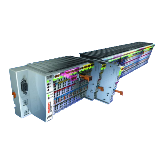
Fig. 2 KL3001, KL3002
Technical Data
Basic Function Principles
Fig. 3 KL3001, KL3002 - Data Flow
Mounting and Wiring
Instructions for ESD Protection
Installation on Mounting Rails
Fig. 4 Spring Contacts of the Beckhoff I/O Components
Fig. 5 Attaching on Mounting Rail
Fig. 6 Disassembling of Terminal
Fig. 7 Power Contact on Left Side
Installation Instructions for Enhanced Mechanical Load Capacity
Connection
Connection System
Fig. 8 Standard Wiring
Fig. 9 Pluggable Wiring
Fig. 10 High Density Terminals
Wiring
Fig. 11 Connecting a Cable on a Terminal Point
Shielding
Connection and LED Description
Fig. 12 KL3001, KL3002 - Connection and Leds
ATEX - Special Conditions (Standard Temperature Range)
ATEX - Special Conditions (Extended Temperature Range)
ATEX Documentation
Configuration Software KS2000
KS2000 - Introduction
Fig. 13 KS2000 Configuration Software
Sample Program for KL Register Communication Via Ethercat on KL3314 Exemplary
Fig. 14: Settings of KL3314 Via Visualisation of Twincat 3
Fig. 15 Opening the *. Tnzip Archive
Fig. 16 Search of the Existing HW Configuration for the Ethercat Configuration of the Example
Access from the User Program
Terminal Configuration
Fig. 17 Mapping in the Lightbus Coupler - Example for KL3002
Fig. 18 Mapping in the Profibus Coupler - Example for KL3002
Mapping in the Bus Coupler
Kl3001
Fig. 19 Mapping in the Interbus Coupler - Example for KL3002
Kl3002
Register Overview
Register Description
Control and Status Byte
Process Data Exchange
Register Communication
Fig. 20 Register Mode Control Byte
Examples of Register Communication
Example 1: Reading the Firmware Version from Register 9
Example 2: Writing to an User Register
Appendix
Support and Service
Advertisement
Quick Links
Download this manual
Documentation
KL3001, KL3002
Single- and Dual-Channel Analog Input Terminals, -10V to +10V
Version:
Date:
4.2
2019-10-08
Table of
Contents
Previous
Page
Next
Page
1
2
3
4
5
Advertisement
Table of Contents
Need help?
Do you have a question about the KL3001 and is the answer not in the manual?
Ask a question
Questions and answers
Related Manuals for Beckhoff KL3001
Control Systems Beckhoff KL3002 Documentation
Single- and dual-channel analog input terminals (46 pages)
Control Systems Beckhoff CX8190 Manual
Embedded pc with ethernet (72 pages)
Control Systems Beckhoff XPlanar Operating Instructions Manual
Planar motor system (89 pages)
Control Systems Beckhoff TF5200 Manual
Clamp position offsets (15 pages)
Control Systems Beckhoff CX8191 Manual
Embedded-pc for bacnet/ip (68 pages)
Control Systems Beckhoff EK1110 Documentation
Ethercat extension (51 pages)
This manual is also suitable for:
Kl3002
Table of Contents
Print
Rename the bookmark
Delete bookmark?
Delete from my manuals?
Login
Sign In
OR
Sign in with Facebook
Sign in with Google
Upload manual
Upload from disk
Upload from URL


Need help?
Do you have a question about the KL3001 and is the answer not in the manual?
Questions and answers