Table of Contents
Advertisement
Advertisement
Chapters
Table of Contents

Related Manuals for Beckhoff EK1110


Summary of Contents for Beckhoff EK1110
- Page 1 Documentation EK1110, EK1110-0008 EtherCAT Extension Version: Date: 2017-05-29...
-
Page 3: Table Of Contents
ATEX Documentation ........................ 34 4.11 UL notice............................ 34 5 Commissioning............................ 36 EK1110 - Configuration by means of the TwinCAT System Manager.......... 36 6 Error handling and diagnostics ...................... 38 Diagnostic LED .......................... 38 7 Appendix .............................. 39 EtherCAT AL Status Codes ...................... 39 Firmware compatibility ........................ - Page 4 Table of contents Version: 2. EK1110, EK1110-0008...
-
Page 5: Foreword
The TwinCAT Technology is covered, including but not limited to the following patent applications and patents: EP0851348, US6167425 with corresponding applications or registrations in various other countries. ® EtherCAT is registered trademark and patented technology, licensed by Beckhoff Automation GmbH, Germany Copyright © Beckhoff Automation GmbH & Co. KG, Germany. -
Page 6: Safety Instructions
All the components are supplied in particular hardware and software configurations appropriate for the application. Modifications to hardware or software configurations other than those described in the documentation are not permitted, and nullify the liability of Beckhoff Automation GmbH & Co. KG. Personnel qualification This description is only intended for trained specialists in control, automation and drive engineering who are familiar with the applicable national standards. -
Page 7: Documentation Issue Status
Associated and synonymous with each revision there is usually a description (ESI, EtherCAT Slave Information) in the form of an XML file, which is available for download from the Beckhoff web site. From 2014/01 the revision is shown on the outside of the IP20 terminals, see Fig. “EL5021 EL terminal, standard IP20 IO device with batch number and revision ID (since 2014/01)”. - Page 8 Production lot/batch number/serial number/date code/D number The serial number for Beckhoff IO devices is usually the 8-digit number printed on the device or on a sticker. The serial number indicates the configuration in delivery state and therefore refers to a whole production batch, without distinguishing the individual modules of a batch.
-
Page 9: Fig. 1 El5021 El Terminal, Standard Ip20 Io Device With Batch Number And Revision Id (Since 2014/01)
Examples of markings Fig. 1: EL5021 EL terminal, standard IP20 IO device with batch number and revision ID (since 2014/01) Fig. 2: EK1100 EtherCAT coupler, standard IP20 IO device with batch number Fig. 3: CU2016 switch with batch number EK1110, EK1110-0008 Version: 2. -
Page 10: Fig. 4 El3202-0020 With Batch Numbers 26131006 And Unique Id-Number 204418
Fig. 5: EP1258-00001 IP67 EtherCAT Box with batch number 22090101 and unique serial number 158102 Fig. 6: EP1908-0002 IP67 EtherCAT Safety Box with batch number 071201FF and unique serial number 00346070 Fig. 7: EL2904 IP20 safety terminal with batch number/date code 50110302 and unique serial number 00331701 Version: 2. EK1110, EK1110-0008... -
Page 11: Fig. 8 Elm3604-0002 Terminal With Id Number (Qr Code) 100001051 And Unique Serial Number 44160201
Foreword Fig. 8: ELM3604-0002 terminal with ID number (QR code) 100001051 and unique serial number 44160201 EK1110, EK1110-0008 Version: 2. -
Page 12: Product Overview
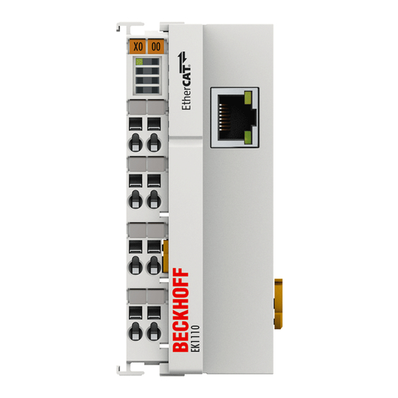
Ethernet cable with RJ 45 or rather M8 connector, thereby extending the EtherCAT strand electrically isolated by up to 100 m. In the EK1110 (EK1110-0008) terminal, the E-bus signals are converted on the fly to 100BASE-TX Ethernet signal representation. Power supply of both terminals to the electronics is via the E-bus. -
Page 13: Technical Data
ATEX [} 32] cULus [} 34] cULus [} 34] Start For commissioning: • mount the EK1110 as described in the chapter Mounting and wiring [} 20] • configure the EK1110 in TwinCAT as described in chapter Parameterization and commissioning [} 36]. EK1110, EK1110-0008 Version: 2. -
Page 14: Basics Communication
Protocol structure: The process image allocation is freely configurable. Data are copied directly in the I/O terminal to the desired location within the process image: no additional mapping is required. The available logical address space is with very large (4 GB). Version: 2. EK1110, EK1110-0008... -
Page 15: Fig. 11 Ethercat Topology
IEEE 1588 standard. In contrast to fully synchronous communication, where synchronization quality suffers immediately in the event of a communication fault, distributed aligned clocks have a high degree of tolerance vis-à-vis possible fault-related delays within the communication system. EK1110, EK1110-0008 Version: 2. - Page 16 In addition to the new Bus Terminals with E-Bus connection (ELxxxx), all Bus Terminals from the familiar standard range with K-bus connection (KLxxxx) can be connected via the BK1120 or BK1250 Bus Coupler. This ensures compatibility and continuity with the existing Beckhoff Bus Terminal systems. Existing investments are protected.
-
Page 17: Ethercat Basics
Due to automatic cable detection (auto-crossing) symmetric (1:1) or cross-over cables can be used between EtherCAT devices from Beckhoff. Recommended cables Suitable cables for the connection of EtherCAT devices can be found on the Beckhoff web- site! Note E-Bus supply A bus coupler can supply the EL terminals added to it with the E-bus system voltage of 5 V;... -
Page 18: Ethercat State Machine
PDO mapping or the sync manager PDO assignment. In this state the settings for the process data transfer and perhaps terminal-specific parameters that may differ from the default settings are also transferred. Version: 2. EK1110, EK1110-0008... -
Page 19: Coe - Interface: Notes
4.2 seconds) • The EtherCAT master automatically synchronizes the local clock with the master clock in the EtherCAT bus with a precision of < 100 ns. For detailed information please refer to the EtherCAT system description. EK1110, EK1110-0008 Version: 2. -
Page 20: Mounting And Wiring
A list of the EtherCAT cable, power cable, sensor cable, Ethernet-/EtherCAT connectors and the field assembled connectors can be found at the following link: http://download.beckhoff.com/download/ document/catalog/main_catalog/english/Beckhoff_EtherCAT-Box-Accessories.pdf You can find the corresponding data sheets at the following link: http://beckhoff.de/english/fieldbus_box/ data_sheets.htm?id=69033899254355 EtherCAT cable Fig. 14: ZK1090-3131-0xxx... - Page 21 Mounting and wiring M8 Connector pin assignment Signal Description Pin (M8) Transmit Data+ Transmit Data- Receive Data+ Receive Data- Shield Shielding Housing EK1110, EK1110-0008 Version: 2.
-
Page 22: Nut Torque For Connectors
Mounting and wiring Nut torque for connectors For usage of the EtherCAT connector M8 of EK1110-0008 the following have to be noticed: M8 connectors It is recommended to pull the M8 connectors tight with a nut torque of 0.4 Nm. When using the torque control screwdriver ZB8800 is also a max. -
Page 23: Fig. 16 Attaching On Mounting Rail
To mount the mounting rails with a height of 7.5 mm under the terminals and couplers, you should use flat mounting connections (e.g. countersunk screws or blind rivets). EK1110, EK1110-0008 Version: 2. -
Page 24: Fig. 17 Disassembling Of Terminal
PE power contact The power contact labeled PE can be used as a protective earth. For safety reasons this contact mates first when plugging together, and can ground short-circuit currents of up to 125 A. Version: 2. EK1110, EK1110-0008... -
Page 25: Installation Instructions For Enhanced Mechanical Load Capacity
10 frequency runs in 3 axes 6 Hz < f < 60 Hz displacement 0.35 mm, constant amplitude 60.1 Hz < f < 500 Hz acceleration 5 g, constant amplitude Shocks 1000 shocks in each direction, in 3 axes 25 g, 6 ms EK1110, EK1110-0008 Version: 2. -
Page 26: Installation Positions
EL/KL terminals to face forward (see Fig. “Recommended distances for standard installation position”). The terminals are ventilated from below, which enables optimum cooling of the electronics through convection. "From below" is relative to the acceleration of gravity. Version: 2. EK1110, EK1110-0008... -
Page 27: Fig. 19 Recommended Distances For Standard Installation Position
Other installation positions All other installation positions are characterized by different spatial arrangement of the mounting rail - see Fig “Other installation positions”. The minimum distances to ambient specified above also apply to these installation positions. EK1110, EK1110-0008 Version: 2. -
Page 28: Connection System
Standard wiring Fig. 21: Standard wiring The terminals of KLxxxx and ELxxxx series have been tried and tested for years. They feature integrated screwless spring force technology for fast and simple assembly. Version: 2. EK1110, EK1110-0008... -
Page 29: Fig. 22 Pluggable Wiring
Ultrasonically “bonded" conductors It is also possible to connect the Standard and High Density Terminals with ultrasonically "bonded" (ultrasonically welded) conductors. In this case, please note the tables concern- Note ing the wire-size width [} 30] below! EK1110, EK1110-0008 Version: 2. -
Page 30: Fig. 24 Mounting A Cable On A Terminal Connection
0.14... 0.75 mm Wire size width (single core wires) 0.08 ... 1.5 mm Wire size width (fine-wire conductors) 0.25 ... 1.5 mm Wire size width (ultrasonically “bonded" conductors) only 1.5 mm (see notice [} 29]!) Wire stripping length 8 ... 9 mm Version: 2. EK1110, EK1110-0008... -
Page 31: Mounting Of Passive Terminals
E-Bus To ensure an optimal data transfer, you must not directly string together more than 2 Passive Terminals! Examples for mounting passive terminals (highlighted) Fig. 25: Correct configuration Fig. 26: Incorrect configuration EK1110, EK1110-0008 Version: 2. -
Page 32: Atex - Special Conditions (Standard Temperature Range)
• EN 60079-0:2012+A11:2013 • EN 60079-15:2010 Marking The Beckhoff fieldbus components with standard temperature range certified for potentially explosive areas bear one of the following markings: II 3G KEMA 10ATEX0075 X Ex nA IIC T4 Gc Ta: 0 … 55°C II 3G KEMA 10ATEX0075 X Ex nC IIC T4 Gc Ta: 0 … 55°C Version: 2. -
Page 33: Atex - Special Conditions (Extended Temperature Range)
• EN 60079-0:2012+A11:2013 • EN 60079-15:2010 Marking The Beckhoff fieldbus components with extended temperature range (ET) certified for potentially explosive areas bear the following marking: II 3G KEMA 10ATEX0075 X Ex nA IIC T4 Gc Ta: -25 … 60°C II 3G KEMA 10ATEX0075 X Ex nC IIC T4 Gc Ta: -25 … 60°C EK1110, EK1110-0008 Version: 2. -
Page 34: Atex Documentation
Beckhoff EtherCAT modules are intended for use with Beckhoff’s UL Listed EtherCAT Sys- tem only. Examination For cULus examination, the Beckhoff I/O System has only been investigated for risk of fire and electrical shock (in accordance with UL508 and CSA C22.2 No. 142). For devices with Ethernet connectors Not for connection to telecommunication circuits. - Page 35 A voltage source complying with NEC class 2 may not be connected in series or parallel with another NEC class 2 compliant voltage supply! These requirements apply to the supply of all EtherCAT bus couplers, power adaptor terminals, Bus Terminals and their power contacts. EK1110, EK1110-0008 Version: 2.
-
Page 36: Commissioning
System Manager TwinCAT tree Enter the EK1110/ EK1110-0008 as an EtherCAT (Direct mode) device in the TwinCAT System Manager in Config mode under Devices. Any Terminals already connected to the network can also be read. This will cause all the Bus Couplers with Bus Terminals and their configurations to be loaded. You can then adapt these to meet your requirements. - Page 37 Initialization error occurred 0x010_ Slave not present 0x020_ Slave signals link error 0x040_ Slave signals missing link 0x080_ Slave signals unexpected link 0x100_ Communication port A 0x200_ Communication port B 0x400_ Communication port C 0x800_ Communication port D EK1110, EK1110-0008 Version: 2.
-
Page 38: Error Handling And Diagnostics
Error handling and diagnostics Error handling and diagnostics Diagnostic LED Fig. 29: EK1110/ EK1110-0008 LEDs for fieldbus diagnostics Display State Description LINK / ACT gree no connection on the EtherCAT strand (X1) linked EtherCAT device connected flashing active Communication with EtherCAT device... -
Page 39: Appendix
The EK1110 has no firmware. Firmware Update EL/ES/EM/EPxxxx This section describes the device update for Beckhoff EtherCAT slaves from the EL/ES, EM, EK and EP series. A firmware update should only be carried out after consultation with Beckhoff support. Storage locations An EtherCAT slave stores operating data in up to 3 locations: •... -
Page 40: Fig. 30 Device Identifier Consisting Of Name El3204-0000 And Revision -0016
Corresponding updates Note should only be carried out in consultation with Beckhoff support. Display of ESI slave identifier The simplest way to ascertain compliance of configured and actual device description is to scan the EtherCAT boxes in TwinCAT mode Config/FreeRun: Version: 2. -
Page 41: Fig. 31 Scan The Subordinate Field By Right-Clicking On The Ethercat Device In Config/Freerun Mode
In this example in Fig. "Change dialog", an EL3201-0000-0017 was found, while an EL3201-0000-0016 was configured. In this case the configuration can be adapted with the Copy Before button. The Extended Information checkbox must be set in order to display the revision. EK1110, EK1110-0008 Version: 2. -
Page 42: Fig. 34 Eeprom Update
Most EtherCAT devices read a modified ESI description immediately or after startup from the INIT. Some communication settings such as distributed clocks are only read during Note power-on. The EtherCAT slave therefore has to be switched off briefly in order for the change to take effect. Version: 2. EK1110, EK1110-0008... -
Page 43: Fig. 36 Display Of El3204 Firmware Version
• offline: The EtherCAT Slave Information ESI/XML may contain the default content of the CoE. This CoE directory can only be displayed if it is included in the ESI (e.g. "Beckhoff EL5xxx.xml"). The Advanced button must be used for switching between the two views. -
Page 44: Fig. 37 Firmware Update
Switch to the Online tab to update the controller firmware of a slave, see Fig. "Firmware Update". Fig. 37: Firmware Update Proceed as follows, unless instructed otherwise by Beckhoff support. • Switch slave to INIT (A) • Switch slave to BOOTSTRAP •... -
Page 45: Fig. 38 Fpga Firmware Version Definition
Fig. 39: Context menu Properties The Advanced Settings dialog appears where the columns to be displayed can be selected. Under Diagnosis/Online View select the '0002 ETxxxx Build' check box in order to activate the FPGA firmware version display. EK1110, EK1110-0008 Version: 2. -
Page 46: Fig. 40 Dialog Advanced Settings
Updating an EtherCAT device In the TwinCAT System Manager select the terminal for which the FPGA firmware is to be updated (in the example: Terminal 5: EL5001) and click the Advanced Settings button in the EtherCAT tab. Version: 2. EK1110, EK1110-0008... -
Page 47: Fig. 41 Select Dialog Advanced Settings
Appendix Fig. 41: Select dialog Advanced Settings The Advanced Settings dialog appears. Under ESC Access/E²PROM/FPGA click on Write FPGA button, Fig. 42: Select dialog Write FPGA EK1110, EK1110-0008 Version: 2. - Page 48 The firmware and ESI descriptions of several devices can be updated simultaneously, provided the devices have the same firmware file/ESI. Fig. 44: Multiple selection and firmware update Select the required slaves and carry out the firmware update in BOOTSTRAP mode as described above. Version: 2. EK1110, EK1110-0008...
-
Page 49: Support And Service
Beckhoff's branch offices and representatives Please contact your Beckhoff branch office or representative for local support and service on Beckhoff products! The addresses of Beckhoff's branch offices and representatives round the world can be found on her internet pages: http://www.beckhoff.com You will also find further documentation for Beckhoff components there. - Page 50 Mounting a cable on a terminal connection ................. Fig. 25 Correct configuration ........................Fig. 26 Incorrect configuration ........................ Fig. 27 TwinCAT tree EK1110/ EK1110-0008 ..................Fig. 28 State, "Online" tab ........................Fig. 29 EK1110/ EK1110-0008 ........................ Fig. 30 Device identifier consisting of name EL3204-0000 and revision -0016 ........
- Page 51 List of illustrations Fig. 42 Select dialog Write FPGA ......................Fig. 43 Select file ............................ Fig. 44 Multiple selection and firmware update ..................EK1110, EK1110-0008 Version: 2.
Need help?
Do you have a question about the EK1110 and is the answer not in the manual?
Questions and answers