Table of Contents
Advertisement
Quick Links
Advertisement
Table of Contents

Related Manuals for Beckhoff XPlanar


Summary of Contents for Beckhoff XPlanar
- Page 1 Operating Instructions | EN XPlanar Planar Motor System 1/19/2021 | Version 1.0...
-
Page 3: Table Of Contents
Version numbers............................... 7 Scope of the documentation .......................... 7 Staff qualification............................... 8 Safety and instruction ............................. 10 Explanation of symbols ........................... 10 Beckhoff Services ............................ 12 For your safety.............................. 13 Safety pictograms ............................ 13 General safety instructions .......................... 14 Product overview............................... 16 Tiles ................................ - Page 4 Cleaning materials ............................ 80 Intervals ................................ 81 Accessories................................ 82 Fan.................................. 82 Cover plug M8.............................. 82 Cover plug M12............................... 82 Connector for ZC2000-0000-00xx ........................ 83 Torque wrench .............................. 83 Decommissioning.............................. 84 Disassembly.............................. 84 Disposal ................................ 85 Index ................................... 86 ─── XPlanar Version: 1.0...
-
Page 5: Documentation Notes
Ether- CAT G10®, EtherCAT P®, Safety over EtherCAT®, TwinSAFE®, 1.1.1 XFC®, XTS® and XPlanar® are registered and licensed trademarks of Beckhoff Automation GmbH. The use of other brand names or designations by third parties may lead to an infringement of the rights of the owners of the corre- sponding designations. - Page 6 • Use of untrained personnel • Use of unauthorized spare parts Copyright © Beckhoff Automation GmbH & Co. KG, Germany 1.1.4 The copying, distribution and utilization of this document as well as the communication of its contents to others without express autho- rization is prohibited.
-
Page 7: Version Numbers
Product features Only the product properties specified in the current operating in- structions are valid. Further information given on the product pages of the Beckhoff homepage, in emails or in other publications is not authoritative. Scope of the documenta- Apart from these operating instructions, the following documents are... -
Page 8: Staff Qualification
Trained specialists have received specific technical training and have specific technical knowledge and experience. Trained special- ists can: • apply relevant standards and directives • assess tasks that they have been assigned • recognize possible hazards • prepare and set up workplaces ─── XPlanar Version: 1.0... - Page 9 They are familiar with relevant standards and directives. Quali- fied electricians can: • independently recognize, avoid and eliminate sources of danger • implement specifications from the accident prevention regula- tions • assess the work environment • independently optimize and carry out their work Version: 1.0 XPlanar ───...
-
Page 10: Safety And Instruction
1.6.1 DANGER Failure to observe will result in serious or fatal injuries. WARNING Failure to observe may result in serious or fatal injuries. CAUTION Failure to observe may result in minor or moderate injuries. ─── XPlanar Version: 1.0... - Page 11 In the case of documentation on a monitor screen, use the zoom function to enlarge the QR code and reduce the distance. Version: 1.0 XPlanar ───...
-
Page 12: Beckhoff Services
Beckhoff and the worldwide partner companies offer comprehensive support and service. Support The Beckhoff Support offers technical advice on the use of individ- ual Beckhoff products and system planning. The employees support 1.7.1 you in the programming and commissioning of complex automation systems. -
Page 13: For Your Safety
Safety pictograms On Beckhoff products you will find attached or lasered safety pic- tograms, which vary depending on the product. They serve to pro- tect people and to prevent damage to the products. Safety pic- tograms must not be removed and must be legible for the user. -
Page 14: General Safety Instructions
Read the documentation prepared by the machine manufac- turer. Before operation Danger from magnetic fields 2.2.1 Magnetic fields on individual components of the XPlanar unit pose a risk to: • people fitted with cardiac pacemakers • persons with magnetically conducting implants • implanted and external defibrillators •... - Page 15 Do not work on live electrical parts Ensure proper connection of the protective conductor. Never loosen electrical connections when live. Do not work on the XPlanar unit until the voltage has dropped below 10 V. Disconnect all compo- nents from the mains and secure them against being switched on again.
-
Page 16: Product Overview
Elongated hole for positioning with locating pins Status LEDs X103, fan X102 OUT with status LED, EtherCAT G Hole for positioning with locating pins X101 IN with status LED, EtherCAT G X100, power supply 24 V / 100 - 240 V Name plate Basic profile Cover ─── XPlanar Version: 1.0... - Page 17 X103 fan connection output X102 OUT EtherCAT connection 2 output Status LED X102 OUT EtherCAT connection 2 output X101 IN EtherCAT connection 1 input Status LED X101 IN EtherCAT connection 1 input X100 power connection input Version: 1.0 XPlanar ───...
- Page 18 ConFig mode in TwinCAT Error in EtherCat G data connection ECAT Error Lights up red Error in EtherCat G data connection X102 OUT Flashing green Data cable plugged into X102 OUT X101 IN Flashing green Data cable plugged into X101 IN ─── XPlanar Version: 1.0...
-
Page 19: Mover
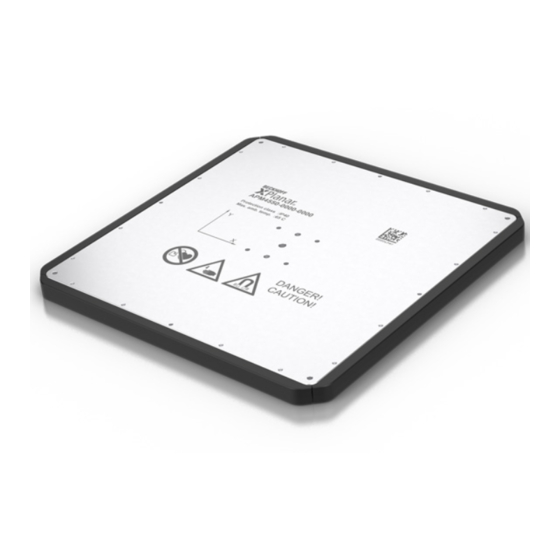
Locating hole for mounting tools, 2 x Thread for mounting tools, 4 x Bumper For further information on the threads and holes for mounting tools, please refer to the chapters on "Dimensional drawings", [Page 34] and "Fixing points", [Page 68]. Version: 1.0 XPlanar ───... - Page 20 For further information on the threads and holes for mounting tools, please refer to the chapters on "Dimensional drawings", [Page 34] and "Fixing points", [Page 68]. Name plate 3.2.1 3.2.1 Number Explanation Product designation Data Matrix code with BTN ─── XPlanar Version: 1.0...
- Page 21 Degrees of freedom 3.2.3 3.2.3 The movers have six degrees of freedom and can be moved along the following axes: Axis Movement Procedure Procedure Raise / Lower Tilting around x-axis Tilting around y-axis Rotating around z-axis Version: 1.0 XPlanar ───...
-
Page 22: Components
Product overview Components A complete XPlanar system consists of: • Tiles • Movers • Power cables • EtherCAT G cables The individual components are defined via the type key and can be ordered separately or preconfigured as a complete system. Tile A system consists of individual tiles that are combined in a machine bed to form a stator surface. - Page 23 The APM4550-0000 is the largest and most powerful mover in the APM4xxx family. It measures 235 x 235 mm. A large number of screw-on points enable mounting of more complex, individual work- piece carriers and attached parts. Version: 1.0 XPlanar ───...
- Page 24 ZC2000‑0000‑0018 The 4-way star distributor supplies power to up to four tiles. Plug: 4 x M12, K-coded 5 m supply cable ZC2000‑0000‑0017 The 6-way star distributor supplies power to up to six tiles. Plug: 6 x M12, K-coded 5 m supply cable ─── XPlanar Version: 1.0...
- Page 25 The cable enables data exchange between tiles and is available in different lengths. This cable can be used to establish a daisy chain connection. Plug: M12 to M12, X-coded Order number Explanation ZK1096-8181-0xxx 0xxx - cable length: 0005 - 0.5 m cable … 0100 - 10 m cable Version: 1.0 XPlanar ───...
-
Page 26: Product Characteristics
Alternatively, the tiles can be com- bined to create long travel paths. Examples of solutions that can be implemented: • Setting up a waiting zone • Overtaking sections to avoid congestion • Combination of outward and return movement • Circular movements ─── XPlanar Version: 1.0... -
Page 27: Data Matrix Code
This example shows how to read the BTN number on a smart- phone screen after a scan. ► Scan the Data Matrix code [1] ► Read the BTN number [2] from the screen of your end device via the camera app or the reader app 0000aae8 Version: 1.0 XPlanar ───... -
Page 28: Intended Use
The components must be installed in electrical systems or machines and may only be put into operation as integrated components of the system or machine. All components of the XPlanar are intended only to be programmed and commissioned with the help of the Beckhoff TwinCAT automa- tion software. -
Page 29: Technical Data
200 mm/s. The synchronization accuracy depends on the load on the movers and the associated inertias in all 6 spatial directions, the controller settings, the target velocity and also any mechanical mis- alignment between the tiles. Version: 1.0 XPlanar ───... -
Page 30: Data For Operation And Environment
Permissible humidity in operation 15 % to 95 % relative humidity, no condensation Degree of pollution 2 according to IEC 60664-1 * For applications at greater installation altitudes, please contact your local Beckhoff office or support@beck- hoff.com Specifications for intended use Ventilation via convection Insulation material class F according to IEC 60085;... -
Page 31: Tiles
Velocity [m/s] Acceleration without payload [m/s Maximum payload at 1 mm flight height [kg] Surface Aluminum housing (blasted), underside plastic film Dimensions [mm] 113 x 113 x 12 155 x 155 x 12 235 x 235 x 12 Version: 1.0 XPlanar ───... -
Page 32: Xplanar
Average power consumption per mover at 1 mm flight height 4220 4330 4550 without load, standstill [W] with 1.5 kg load, standstill [W] * For further information contact your local Beckhoff office or support@beckhoff.com. Mechanical data Tiles 4322 Length [mm] Width [mm] Height [mm] Weight [g]... - Page 33 ± 200 A-axis [mrad / °] ± 5 / ± 0.29 B-axis [mrad / °] ± 5 / ± 0.29 C-axis [mrad / °] ± 5 / ± 0.29 Absolute accuracy XY-axis [µm] ± 150 Z-axis [µm] ± 150 A-axis [mrad / °] ± 5 / ± 0.29 B-axis [mrad / °] ± 5 / ± 0.29 C-axis [mrad / °] ± 5 / ± 0.29 Number of movers per CPU core 1 - 2 * For further information contact your local Beckhoff office or support@beckhoff.com. Version: 1.0 XPlanar ───...
-
Page 34: Dimensional Drawings
Technical data Dimensional drawings Dimensional drawings and 3D models online You have the possibility to download the dimensional drawings and 3D models of the individual components from the Beckhoff website: www.beckhoff.de/download Tiles • All figures in millimeters 4.7.1 APS4322-0000 240 - 0,3... - Page 35 98 □ 86 □ M4 x 6 (4x) Ø4 H7 x 4,5 (2x) APM4330-0000 155 □ 12,1 140 □ 128 □ M4 x 6 (4x) 32 □ M4 x 6 (4x) Ø4 H7 x 8 (2x) Version: 1.0 XPlanar ───...
- Page 36 Technical data APM4550-0000 235 □ 12,1 220 □ 208 □ M4 x 6 (4x) 32 □ M4 x 6 (4x) Ø4 H7 x 8 (2x) ─── XPlanar Version: 1.0...
- Page 37 Technical data Machine bed sample design • All figures in millimeters 4.7.3 1 x 1 (240) 0,012 5 H7 (2x) 6,4 (6x) - 0 , 000 Version: 1.0 XPlanar ───...
- Page 38 Drilling pattern for fastening with two screws Position of the elongated hole in the tile Drilling pattern for fastening with four screws Position of the locating hole in the tile Ensure there is sufficient space at the corners ─── XPlanar Version: 1.0...
- Page 39 240 ± 0,1 □ 220,4 ± 0,1 A- A ( 1 : 2 ) □ 214 ± 0,1 □ 207,3 ± 0,1 170 ± 0,1 80 ± 0,1 6 ± 0,1 Ø6 (80x) Ø3,3 (80x) 3,5 (80x) Version: 1.0 XPlanar ───...
- Page 40 Technical data Assembly aid sample design • All figures in millimeters 4.7.5 226 ± 0,2 ≥12 Ø 5,5 (4x) ─── XPlanar Version: 1.0...
-
Page 41: Scope Of Supply
Protect the packaging against wetness. The contents are fragile. Label Symbol Explanation The carton contains electrostatically sensitive compo- nents. The table below shows the dimensions of the packages: • All dimensions in mm Carton Height Width Depth Tiles Mover Version: 1.0 XPlanar ───... -
Page 42: Transport And Storage
Long-term storage Perform recurring inspections Check the XPlanar state and condition every six months. Damage to the XPlanar or failure to carry out maintenance can shorten the service life of the installed components and parts. Prevent the formation of condensation Keep the ambient temperature constant. -
Page 43: Mechanical Installation - Part 1: Tiles
3 x 4 tiles as an example. Observe the order of assembly Assemble the XPlanar one step at a time. Insert the tiles one after the other into the machine bed. This avoids complications with po- sitioning and mounting individual tiles at the end of the first part of the mechanical installation. -
Page 44: Tile
Thread for mounting on the machine bed with four screws* Elongated hole for locating pin Thread for mounting on the machine bed with two screws* Locating pin hole Point of origin * To fix the tile with six screws, use fixing points [1] and [3] ─── XPlanar Version: 1.0... - Page 45 The length of the screws [1] and locating pins [2] for fixing the tiles depends on the height X of the machine bed [3]. Beckhoff recommends the following screw depths in the tile: • The M6 screws [1] for fastening the tiles should protrude be- tween 6 and 9 mm from the machine bed [3].
- Page 46 ► Fasten the tile [1] with two screws [2] ► Observe tightening torques Component Tightening torque [Nm] M6 screws With four screws ► Fasten the tile [1] with four screws [2] ► Observe tightening torques Component Tightening torque [Nm] M6 screws ─── XPlanar Version: 1.0...
- Page 47 An incorrectly installed tile leads to problems with the mover control via the software. Number Name Connections Point of origin Make sure that all tiles have the same orientation. Use the bottom cover with the connections [1] as a guide for correct alignment of the tiles. Version: 1.0 XPlanar ───...
- Page 48 ► Note the tile orientation ► Fasten the additional tile [1] with two, four or six screws [2] ► Observe tightening torques Component Tightening torque [Nm] M6 screws ► Position further tiles and secure them with screws ─── XPlanar Version: 1.0...
- Page 49 Serious or even fatal injuries may result if this is ignored. Beckhoff recommends mechanical protection of the stator surface after all tiles have been fastened to the machine bed. The mechanical protection [1] must protrude at least 16 mm beyond the stator surface [2].
- Page 50 Application of an easy-to-clean surface 7.2.3.2 The application of an easy-to-clean surface facilitates the use of the XPlanar in cleanrooms and in the pharmaceutical and food in- dustries. The surface must not be thicker than 0.5 mm. It must be non-mag- netic and have low electrical conductivity.
- Page 51 Insufficient cooling can cause damage to components due to heat accumulation. Beckhoff recommends mounting a fan [+] on tiles in situations where movers experience strong acceleration, lift or tilt, in order to dissi- pate heat in a targeted manner and to avoid heat accumulation.
- Page 52 ► Plug the connector [1] into port X103 [2] of the tile ► Tighten the locking thread [1] of the connector by turning the knurl Water cooling As an alternative to fan cooling, it is possible to cool the tiles using a 7.2.3.4 water-cooled machine bed. ─── XPlanar Version: 1.0...
-
Page 53: Electrical Installation
Connection technology All XPlanar tiles have interfaces for connecting the power cable and inputs and outputs for EtherCAT G lines. The end of the Ether- CAT G cable ZK1096-8191-0xxx has an RJ45 connector with the TSB568A configuration. -
Page 54: Example Circuit
An example for a power supply involving connecting a star distribu- tor with up to six tiles is provided below: Symmetrical distribution between the phases For multiphase feed networks the XPlanar tile groups must be dis- tributed symmetrically between the existing phases. Observe the maximum possible input inrush current. - Page 55 Electrical installation X100 pin assignment 8.4.1 8.4.1 Number Identification Signal Brown L, 100 - 240 V Blue N, 100 - 240 V + 24 V White GND, 24 V Green/yellow PE Protective earth Version: 1.0 XPlanar ───...
-
Page 56: Installing Cables
► Observe tightening torques: Components Tightening torque [Nm] Power cable connector ► Connect up to five additional tiles to the star distributor and tighten the connectors ► Connect the power cables to all tiles and tighten the connectors ─── XPlanar Version: 1.0... - Page 57 CAT G cables ZK1096-8181-0xxx can be used to connect up to nine further tiles based on the daisy chain principle. Uniform cabling Beckhoff recommends connecting the same tiles that are intercon- nected via the power cable with EtherCAT G cables. Simplified representation In the interest of clarity, only the tiles are shown in EtherCAT G ca-...
- Page 58 ► If used: screw connector [2] to port X102 OUT ► Observe tightening torques: Components Tightening torque [Nm] Connector of the EtherCAT G ca- Cover plug [+] Beckhoff recommends terminating unused connections on the tiles with cover plugs [+]. 8.5.4 Cover plug M8 8.5.4.1 8.5.4.1 ►...
-
Page 59: Grounding The Machine Bed
The ground connection must be made with the largest possible cross-section, with a low impedance, over a large area and via a short connection to large conductive fastenings. Beckhoff recom- mends the use of wide connections with large contact surfaces. - Page 60 Electrical installation Painted surfaces 8.6.1 8.6.1 ► Ground the painted surface with spring washer [1], washer [2], contact washer [3], nut [4] and screw [5] Unpainted surfaces 8.6.2 8.6.2 ► Ground the unpainted surface with spring washer [1], washer [2], nut [3] and screw [4] ─── XPlanar Version: 1.0...
-
Page 61: System Test
Accidental connection of 100 - 240 V instead of 24 V can lead to the destruction of all tiles. ► Connect the entire XPlanar system [1] to the mains supply ► First connect only 24 V ► Check the tile function ►... -
Page 62: Mechanical Installation - Part 2: Mover
The field of the permanent magnets is present even when the power supply is switched off. If the movers attract each other and collide, serious injuries to the fingers from crushing and in the eyes from splinters can result. ─── XPlanar Version: 1.0... - Page 63 ► Remove the fixing packaging [1] with mover [2] from the box [3] B E C K H O F ► Fold down the side parts [1] of the fixing packaging ► Release the fixing [1] of the mover [2] by folding up the fixing packaging [3] Version: 1.0 XPlanar ───...
- Page 64 Mechanical Installation – Part 2: Mover ► Remove the mover [1] with transport securing device [2] from the fixing packaging [3] ─── XPlanar Version: 1.0...
- Page 65 ► Transport the individual mover [1] with the safety pictograms fac- ing upwards in the transport securing device [2] straight to the workplace or system Positioning on a tile 9.1.3 9.1.3 ► Position the mover [1] with transport securing device [2] directly on the tile [3] Version: 1.0 XPlanar ───...
- Page 66 XY axes of the tile. The point of origin of the tile is used for orientation. For more information see chapter on "Mounting", [Page 45]. Also make sure that you position the movers as parallel as possible to the outer edges of the tiles. ─── XPlanar Version: 1.0...
- Page 67 ► Make sure that your fingers are not underneath the tile [3] and that the mover [1] has sufficient distance to other movers ► Remove the transport securing device [1] ► Position the remaining movers on the tiles in the same way Version: 1.0 XPlanar ───...
- Page 68 Mechanical Installation – Part 2: Mover Mounting tools Suitable tools can be mounted on the movers depending on the ap- plication requirements. Beckhoff recommends: 9.1.4 • Using non-magnetic material • Holding the tool as flat as possible • Keeping the tool weight down as far as possible •...
- Page 69 If the safety pictograms are not visible, other persons may not be aware of possible dangers and may be seriously injured during use. Version: 1.0 XPlanar ───...
- Page 70 The dimensional drawings and 3D models for the assembly aids are available for download from the Beckhoff website: www.beckhoff.de/download The assembly aid must be made of non-magnetic material. Beckhoff recommends the following material: • Wood, plastic or aluminum The assembly aid weakens the magnetic field of the movers, but the permanent magnetic field on the underside of the movers is still present.
- Page 71 The screws must not protrude from the frame. The length of the screws [1] for fastening the assembly aid [2] de- pends on the height X of the assembly aid. Beckhoff recommends the following screw depth in the frame [3]: • 10 mm The M5 screws must not protrude from the frame.
- Page 72 ► To safely remove the bumpers, remove the mover [1] from the transport securing device [2] and turn it by 180° ► Place the mover in the transport securing device [2] with the un- derside facing upwards ─── XPlanar Version: 1.0...
- Page 73 ► Remove two screws [1] ► Remove a bumper [2] ► Remove further bumpers in the same way ► Place the frame [1] on the work surface with the top side [2] fac- ing upwards Version: 1.0 XPlanar ───...
- Page 74 Before covering the first mover with an assembly aid, note the ori- entation of the mover in the frame. ► Place the mover [1] into frame [2] ► Secure the mover [1] with the assembly aid [2] and four screws [3] to prevent it from falling out ─── XPlanar Version: 1.0...
- Page 75 Failure to do so may result in serious injury to fingers from crush- ing or to eyes from splinters. ► Turn the frame [1] with attached assembly aids by 180° Version: 1.0 XPlanar ───...
- Page 76 Failure to do so may result in serious injury to fingers from crush- ing or to eyes from splinters. ► Turn the frame [1] with attached movers [2] by 180° ► Carry frame to the system using the assembly aids ─── XPlanar Version: 1.0...
- Page 77 ► Remove the four screws [1] ► Remove the assembly aid [2] from the frame ► Remove further screws and assembly aids in this way Version: 1.0 XPlanar ───...
-
Page 78: Commissioning
• Check the wiring, connection and proper grounding • Remove ferromagnetic objects near the movers • Ensure that there are no foreign objects in the XPlanar plane that could lead to a collision • Make sure the surfaces are not contaminated During commissioning •... -
Page 79: Prerequisites During Operation
Make sure that all movers come completely to a standstill. Movers on vertical tracks can move uncontrollably or fall off the system when the controller is disabled or the 100 - 240 V power supply is disconnected, causing serious injury. Version: 1.0 XPlanar ───... -
Page 80: Maintenance And Cleaning
Do not immerse or spray XPlanar components Wipe the XPlanar components with a clean, lint-free cloth. Cleaning by immersion can lead to damage to the XPlanar compo- nents and surfaces as well as to leak-tightness problems due to im- permissible solutions. -
Page 81: Intervals
Machine bed 6 months Check the fastening of the tiles on the machine bed Mover 11.2.2 Components Interval Maintenance Protective film on the 6 months Check the protective film for wear and damage underside Version: 1.0 XPlanar ───... -
Page 82: Accessories
12.3 The M12 cover plugs can be used to seal unused X100, X101 IN and X102 OUT ports on the tiles: • ZS5000-0020 Scope: • 50 x cover plugs M12, IP67 • Direct link to the data sheet ─── XPlanar Version: 1.0... -
Page 83: Connector For Zc2000-0000-00Xx
1 x connector, M12 K-coded • ZS2020-2721 Torque wrench 12.5 12.5 For controlled screw-mounting of the connectors with a specified torque. • ZB8801-0000 Scope: • Torque setting tool • Torque wrench • Direct link to the data sheet Version: 1.0 XPlanar ───... -
Page 84: Decommissioning
Failure to do so can result in severe crushing and injury to fin- gers. Do not remove components from the products Only Beckhoff Automation GmbH & Co. KG is permitted to remove components. Contact Beckhoff Service if you have any questions. -
Page 85: Disposal
The trans- 13.2.1 port costs are borne by the sender. Send the used devices with the note "For disposal" to: Beckhoff Automation GmbH & Co. KG Gebäude „Service“ Stahlstraße 31 D-33415 Verl In addition, you have the option to contact a local certified specialist company for the disposal of used electrical and electronic appli- ances. -
Page 86: Index
42 Label, see Safety pictograms 13 Support 12 LED status display 18 Surface 50 Symbols 10 System test 61 Machine bed Material 43 Maintenance 80 Target group 8 Intervals 81 Technical data 30 Mechanical protection 49 ─── XPlanar Version: 1.0... - Page 87 46, 48 Tiles Alignment 47 Fixing materials 45 Fixing points 44 Mounting 45 Tool Mounting 69 Transport 42 Transport securing device 65, 72 Type key Mover 21 Tile 18 XPlanar Dismantling 84 Storage 42 Transport 42 Version: 1.0 XPlanar ───...
- Page 89 More Information: www.beckhoff.com/xplanar Beckhoff Automation GmbH & Co. KG Hülshorstweg 20 33415 Verl Germany Phone: +49 5246 9630 info@beckhoff.com www.beckhoff.com...
Need help?
Do you have a question about the XPlanar and is the answer not in the manual?
Questions and answers