
Related Manuals for Beckhoff KL3002


Summarization of Contents
Foreword
Notes on the documentation
Intended audience, disclaimer, trademarks, and patent information.
Safety instructions
Important safety regulations and warnings for device handling and installation.
Documentation issue status
Details on document versions, changes, and issue history.
Beckhoff Identification Code (BIC)
Explanation of the Beckhoff Identification Code (BIC) for product identification.
Product Overview
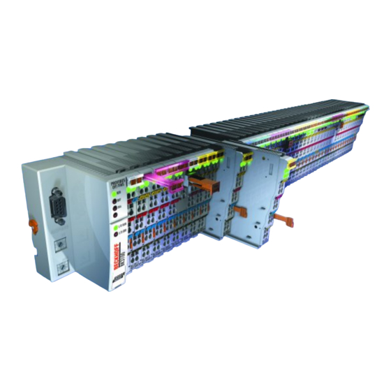
Introduction
Overview of KL3001 and KL3002 analog input terminals and their LEDs.
Technical data
Detailed technical specifications for KL3001 and KL3002 terminals.
Basic function principles
Explanation of analog input terminals, signal processing, and Run LED behavior.
Mounting and wiring
Instructions for ESD protection
Guidelines for preventing electrostatic discharge damage to devices.
Installation on mounting rails
Instructions for mounting bus terminals and couplers on 35 mm DIN rails.
Connections within a bus terminal block
Details on K-Bus/E-Bus spring contacts and power contacts for connections.
PE power contact
Information on using the PE contact as a protective earth connection.
Installation instructions for enhanced mechanical load capacity
Additional instructions for terminals with increased mechanical load capacity.
Connection
Overview of different connection options for Bus Terminal systems.
Standard wiring (ELxxxx / KLxxxx)
Description of standard wiring with integrated spring force technology.
Pluggable wiring (ESxxxx / KSxxxx)
Details on pluggable connection levels for steady wiring and replacement.
High Density Terminals (HD Terminals)
Compact design of HD Terminals with 16 terminal points.
Wiring
Instructions for connecting cables to terminal points using spring force technology.
High Density Terminals (HD Terminals [► 19]) with 16 terminal points
Connecting conductors in HD Terminals using direct plug-in technique.
Shielding
Recommendations for connecting shielded, twisted paired wires.
Connection and LED description
Description of terminal connections and LED indicators for KL3001 and KL3002.
ATEX - Special conditions (standard temperature range)
Special ATEX conditions for using components in potentially explosive areas.
ATEX - Special conditions (extended temperature range)
Special ATEX conditions for extended temperature range in explosive areas.
ATEX Documentation
Information on ATEX documentation and further notes for explosive areas.
Configuration Software KS2000
KS2000 - Introduction
Introduction to KS2000 software for configuration, commissioning, and parameterization.
Sample program for KL register communication via EtherCAT on KL3314 exemplary
Sample application for register communication using EtherCAT on KL3314.
Preparations for starting the sample programs (tnzip file / TwinCAT 3)
Steps to download and prepare sample programs for TwinCAT 3.
Access from the user program
Terminal configuration
Mapping of terminal channels in the Bus Coupler and parameterization methods.
Mapping in the Bus Coupler
How terminals map into the Bus Coupler, including default settings and modifications.
KL3001
Default mapping for KL3001 with various bus coupler types.
KL3002
Default mapping for KL3002 with various bus coupler types.
Register overview
Overview of registers available for each channel of the terminal.
Register description
Detailed descriptions of registers for parameterization and data access.
Control and status byte
Explanation of control and status bytes for terminal communication.
Process data exchange
Control and status byte usage in process data exchange (REG=0).
Register communication
Methods for accessing registers via process data exchange and register mode.
Examples of Register Communication
Examples demonstrating register reading and writing operations.
Example 1: reading the firmware version from Register 9
Example of reading the firmware version using register communication.
Example 2: Writing to an user register
Example of writing to user registers, including code word management.
Appendix
Support and Service
Information on Beckhoff support, branch offices, and service contacts.
Need help?
Do you have a question about the KL3002 and is the answer not in the manual?
Questions and answers