
Related Manuals for Hameg HMO Series


Summary of Contents for Hameg HMO Series
- Page 1 2 5 0 / 3 5 0 M H z D i g i t a l O s c i l l o s c o p e H M O S e r i e s Manual English...
-
Page 2: General Information Regarding The Ce Marking
General information regarding the CE marking HAMEG instruments fulfill the regulations of the EMC directive. The conformity test made by HAMEG is based on the actual generic- and product standards. In cases where different limit values are applicable, HAMEG applies the severer standard. For emission the limits for KONFORMITÄTSERKLÄRUNG... - Page 3 1.6. Maintenance 10.6 Definition of the FILE/PRINT key 1.7. CAT I 1.8. Mains voltage Mixed Signal Operation Familiarize yourself with your new HAMEG 11.1 Logic trigger Digital Storage Oscilloscope 11.2 Display functions of the logic channels 11.3 Cursor measurements for the logic channels Front view...
- Page 4 H M O 3 5 2 4 / H M O 3 5 2 2 3 5 0 M H z 2 / 4 C h a n n e l D i g i t a l O s c i l l o s c o p e H M O 3 5 2 2 / H M O 3 5 2 4 8 Channel logic probe HO3508...
- Page 5 Fields Field 1, field 2, both Line All, selectable line number Sync. Impulse Positive, negative Source CH 1, CH 2, Ext. [CH 1...CH 4] T e c h n i s c h e D a t e n Logic: AND, OR, TRUE, FALSE Source LCH 0…15...
-
Page 6: Installation And Safety Instructions
Removal/fitting of the handle: The handle can be removed in The complete technical datasheet of the HMO2524 position F, pulling the side parts outside the housing. Adding you can find in the internet at www.hameg.com. the handle works vice versa. 1 Installation and safety instructions... - Page 7 Return material authorization (RMA): not be guaranteed do not use the instrument any more and lock Prior to returning an instrument to HAMEG, ask for a RMA it away in a secure place. number either by internet (http://www.hameg.com) or fax (+49 (0) 6182 800 501).
-
Page 8: Front View
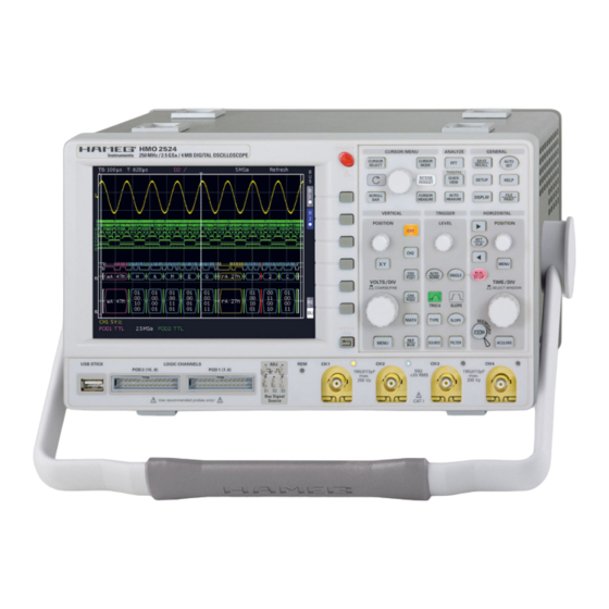
51 50 Fig. 2.1: Frontview of the HMO2524 is clearly set apart by its red colour. The most important 2 Familiarize yourself with your new HAMEG controls are backlighted by coloured LEDs in order to imme- Digital Storage Oscilloscope diately indicate the actual settings. The panel is subdivided in... -
Page 9: Rear View
10 divisions. On the left of the screen area little arrows [1] indicate the reference potentials of The HMO series instruments offer some options which allow you the channels. The line above the graticule contains status and to extend the areas of application considerably. - Page 10 The menus are used as shown in Fig. 2.9 if they concern func- tions which have either to be switched on or where values have HAMEG oscilloscopes are renowned for easy operation, based to set. The choice is between OFF and the value presented. The on a few basic principles which repeat with the diverse settings round arrow in the right corner of the menu window points to and functions.
-
Page 11: Bus Signal Source
At the second page of the basic menu you find the menu for The HMO series is being improved continuously. you are invited firmware and help update, which is explained in detail in the next to download the most recent firmware under www.hameg.com. chapter. The last menu item is the PROBE ADJUST. Pressing Firmware and help are packed into one ZIP data packet. After the soft key leads you to the menu where you can set whether downloading the ZIP data unpack it into an USB stick’s basic... - Page 12 I n t r o d u c t i o n Fig: 2.12: Updating menu and information window Fig. 2.14: Manual licence key input. The licence key will be sent to you by email as an appended data After inputting of the complete key please press the soft menu file (name: SERIAL NUMBER.hlk). This file is an ASCII file and key next to ACCEPT in order to input the key into the system.
- Page 13 Press the top soft key once to change the input coupling to DC. The following chapter is intended to introduce you to the most The actual settings are marked by underlying blue important functions and settings of your new HAMEG HMO fields, repeated pressing of the keys will alternate between the settings.
-
Page 14: Automatic Measurements
Use the time base knob to select the zoom factor and In addition to cursor measurements the most important signal the small knob for horizontal positioning. parameters can be displayed. your HAMEG oscilloscope offers these possibilities: – the definition of the display of 2 parameters which may come from different sources –... -
Page 15: Storing Data
A q u i c k i n t r o d u c t i o n displayed in the right bottom corner of the screen. If you press the softkey beside TYPE you can choose the parameter you want from the list using the general knob. - Page 16 A q u i c k i n t r o d u c t i o n Fig. 3.14: Menu SCREENShOTS Please verify that the USB connector into which you plugged the USB stick (front or rear) is written in the top soft menue (You can change the destination by opening the respective menu if you press the softkey next to STORAGE).
-
Page 17: Vertical System
A q u i c k i n t r o d u c t i o n The passive probes must be adjusted to the inputs 4 Vertical system to which they are connected. See the probe manual for the adjustment procedure. The PROBE ADJUST output is only usable for 1:1 and 10:1 probes, for For the vertical settings there are 100:1 or 1000:1 probes special external generators... -
Page 18: Probe Attenuation Selection
H o r i z o n t a l S y s t e m ( T i m e B a s e ) the left of the display, also visible if the menu was closed. One must be stopped by pushing the RUN/STOP key. While in STOP marker indicates the position, the other the offset (refer to Fig. -
Page 19: Marker Function
H o r i z o n t a l S y s t e m ( T i m e B a s e ) select automatic switching to Random sampling >20 ns/ to change time base settings without leaving the zoom mode. div..The mode can be disabled by pushing the soft key. -
Page 20: Trigger System
STOP mode, indicated by the RUN/STOP key The trigger system of the HMO is lighting up in red. easy to handle by just observing the HAMEG concept of instrument Trigger sources operation. Trigger sources are the 2 or analog channels and the ex- ternal trigger input. If the optional logic probe HO3508 with 8... -
Page 21: Pulse Trigger
T r i g g e r S y s t e m Video trigger The slope trigger can be coupled with a so called „B Trigger“. This option is available after pushing TyPE. This function allows you to adjust the trigger such that first condition „A“ must be met The video trigger allows you to trigger on PAL, NTSC, SECAM and then another condition „B“ before the trigger will respond standard video signals or on HDTV Signals. Select this mode (refer to Fig. - Page 22 D i s p l a y o f s i g n a l s channels D0 to D15, the math functions and the references. 7 Display of signals The analog channels can only use up to ±5 divisions from the center.
- Page 23 D i s p l a y o f s i g n a l s the lowest menu item toggles between HIGH and LOW of the XY key in the VERTICAL section of the front panel; the key will LED’s of all backlit keys and all other LED displays on the light up, and the screen will be partitioned in a large and some front panel.
- Page 24 PEAK LEVELS The most frequently used measurement method with an oscil- This mode provides 2 cursors in order to measure the minimum loscope is the cursor measurement. The HAMEG concept is and maximum values of a signal within the time span as defined oriented towards the expected results and thus provides not by the two cursors.
- Page 25 M e a s u r e m e n t s PEAK-TO-PEAK In this mode the voltage difference between the minimum and maximum values of the displayed signal will be measured. PEAK + In this mode the positive peak value of the displayed signal will be measured.
- Page 26 M e a s u r e m e n t s PULSE WIDTH -: 9 Analysis This mode measures the width of a negative pulse. A negative pulse consists of a falling edge follow by a rising edge. The measurement effects only one the selected channel and needs at least one complete pulse of a triggered signal.
-
Page 27: Formula Editor
A n a l y s i s The upper 3 menu keys allow you to select the sources as well After selecting the operators and the operands, press the soft as the operation. All active channels are available as sources. menu key next to MODIFY to activate DISPLAY (if activated the The available operations are addition and subtraction. -
Page 28: Frequency Analysis (Fft)
A n a l y s i s The information about the settings for the time display will be shown top left, the information about the Zoom and position between both grids and the information about the FFT display (span and center frequency) is shown below the larger area. One of these displays is brighter than the other, after selecting the FFT function this one will be brighter. -
Page 29: Pass/Fail Test Based On Masks
A n a l y s i s Four additional parameters will be displayed in the right bottom corner of the screen: – RMS value – Period – Frequency – Peak-to-peak voltage Only one channel may be activated in the Quickview mode. If another channel is selected by pushing its key, the previously selected one will be deactivated. -
Page 30: Documentation, Storing And Recalling
D o c u m e n t a t i o n , s t o r i n g a n d r e c a l l i n g main instrument settings menu and select lOAD by pushing the 10 Documentation, storing and recalling respective soft menu key. - Page 31 USB stick. (See HRT (HAMEG Reference Time): chapter 10.1 for a detailed description.) Data sets with this code contain data of curves vs. time. If a...
-
Page 32: Sets Of Formulas
D o c u m e n t a t i o n , s t o r i n g a n d r e c a l l i n g 10.4 Screenshots 10.6 Definition of the FILE/PRINT key The most important method of storing for documentation The key FILE/PRINT on the front panel allows you to store purposes is the screen photo. -
Page 33: Mixed Signal Operation (Optional)
M i x e d S i g n a l O p e r a t i o n top soft menu key. (This functionality will be available with a 11 Mixed Signal Operation (optional) firmware 3.0 or later.) The reference criterion can be selected in the menu field below by the respective soft key. -
Page 34: Cursor Measurements For The Logic Channels
M i x e d S i g n a l O p e r a t i o n BIT and NEXT BIT, then use the universal knob for the linking to the logic channel. If you chose the bus type PARALLEL + CLOCk, the lower two soft menu keys are reserved for the source and the slope of the clock. -
Page 35: Serial Bus Analysis (Optional)
S e r i a l b u s a n a l y s i s The soft menu key CONFIGURATION will call a menu which is 12 Serial bus analysis (optional) dependent upon the bus type selected. These menus are de- scribed in the chapters of the respective bus configurations. - Page 36 S e r i a l b u s a n a l y s i s After pressing the soft menu key SLAVE ADDRESS the universal knob can be used to select a 7 or 10 bit address on which shall be triggered. Pressing the soft menu key DATA will open a submenu which allows to enter data in addition to the address.
-
Page 37: Spi Bus Triggering
S e r i a l b u s a n a l y s i s the soft menu key SERIAL BUSES. Subsequently press the key SOURCE in the TRIGGER area and select the SPI bus. (It will only show up if it was previously defined.) Pressing the key FILTER in the TRIGGER area will present all possible trigger options. Triggering is possible on the FRAME START, the FRAME END and in a preselected BIT. (Press the soft menu key BIT and use the universal knob for the selection of the desired bit number. Further trigger possibilities will become available after pres- sing the soft menu key SER. PATTERN, a menu will open which allows to provide for a bit offset which may exist (values from... -
Page 38: Uart/Rs-232 Bus Triggering
S e r i a l b u s a n a l y s i s SIZE and the universal knob are used to select 5 to 9 bits. The key parity allows to select no, even or odd. The last soft menu item on page 1 defines the length of the stop bit as nominal, 1.5 times or twice. -
Page 39: Remote Control Via Interface
The USB interface must be chosen in the oscilloscope and does not need any setting. At the first connection Windows ™ ask for a driver. The driver you can find on the delivered CD or in the internet at www.hameg.com at the download area for the HO720/HO730. The connection can be done via the normal USB or via the virtual COM port. The description how to install the driver you can find in the HO720/730 manual. -
Page 40: List Of Pictures
A p p e n d i x Fig. 9.6: Extended FFT menu 14 Appendix Fig. 9.7 PASS/FAIL mask test. Fig. 10.1: Basic menu for instrument settings 14.1 List of pictures Fig. 10.2: Storing instrument settings Fig. 10.3: Recalling instrument settings Fig. 2.1: Frontview of the HMO2524 Fig. 10.4: Import/Export menu for instrument settings Fig. - Page 41 A p p e n d i x coupling: 13, 17, 20 memory depth: 13, 19 cursor measurements: 10, 14, 24, 34 memory location: 28 Cursor/Menu: 8, 18 mixed-signal operation: 9 CURSOR SELECT: 10, 14, 16, 21, 24, 27 Modulation: 23 CURSOR SELECT-key: 10 multiplication: 26 curves: 9, 22, 23, 30, 31, 32 Negative Duty Cycle:: 26 data manager: 12, 30, 31, 32 NIBBLE: 37...
- Page 42 A p p e n d i x slope: 9, 20, 21, 25, 34, 37 Smoothing: 18 soft key: 8, 10, 11, 13, 14, 15, 16, 17, 18, 19, 20, 21, 24, 31, 33 soft menu keys: 10, 21, 22, 24, 25, 26, 34 sources: 14, 15, 20, 22, 23, 25, 27, 35 Square: 11, 27, 28 square wave signal: 11, 13...
- Page 43 N o t i z e n Subject to change without notice...
-
Page 44: Spectrum Analyzer
Subject to change without notice HAMEG Instruments GmbH 43-2030-2010 (5) 01042010 Industriestraße 6 41-HMOS-00E0 (1) 18082010 Industriestraße 6 © HAMEG Instruments GmbH D-63533 Mainhausen © HAMEG Instruments GmbH D-63533 Mainhausen A Rohde & Schwarz Company Tel +49 (0) 61 82 800-0 A Rohde &...
Need help?
Do you have a question about the HMO Series and is the answer not in the manual?
Questions and answers