Table of Contents
Advertisement
Advertisement
Chapters
Table of Contents

Subscribe to Our Youtube Channel
Related Manuals for Hameg HM 303-4


Summary of Contents for Hameg HM 303-4
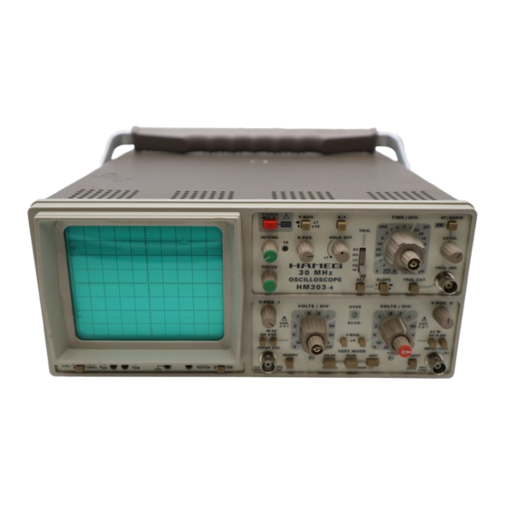
- Page 1 ® Instruments Oscilloscope HM 303-4 SERVICE-MANUAL HM303-4...
-
Page 2: Table Of Contents
Table of contents Service Manual Circuit Diagrams Adjustment Procedure HM303-4 Y-Preamplifier CH I (YP-Board) ........4 Y-Preamplifier CH II (YP-Board) ......... 5 Y-Intermediate Amplifier and Trigger Amplifier (YP-Board) ..............6 YPA-Board (Top side) ..........7 YPA-Board (Bottom side) .......... 8 XY-Amplifier, YF-Amplifier, OS-Circuit ....... - Page 3 Subject to change without notice...
-
Page 4: Specifications
The bandwidth has been extended from 20 to 30MHz, the sweep Horizontal Deflection rate increased to 10ns/div. and improvements added to the already legendary HAMEG auto triggering system. The HM303 is the ideal instrument for waveform Time coefficients: 20 calibrated steps display in the DC to 100MHz frequency range. -
Page 5: Y-Preamplifier Ch I (Yp-Board)
Y-Preamplifier CH I (YP-Board) Subject to change without notice... -
Page 6: Y-Preamplifier Ch Ii (Yp-Board)
Y-Preamplifier CH II (YP-Board) Subject to change without notice... -
Page 7: Y-Intermediate Amplifier And Trigger Amplifier (Yp-Board)
Y-Intermediate Amplifier and Trigger Amplifier (YP-Board) Subject to change without notice... -
Page 8: Ypa-Board (Top Side)
YPA-Board (Top side) Subject to change without notice... -
Page 9: Ypa-Board (Bottom Side)
YPA-Board (Top side) Subject to change without notice... -
Page 10: Xy-Amplifier, Yf-Amplifier, Os-Circuit
XY- Amplifier, YF- Amplifier, OS- Circuit Subject to change without notice... -
Page 11: Xy-Board (Top Side)
XY Board (Top side) Subject to change without notice... -
Page 12: Xy-Board (Bottom Side)
XY Board (Top side) Subject to change without notice... -
Page 13: Sync.-Amplifier
Sync.- Amplifier Subject to change without notice... -
Page 14: Time Base
Time base Subject to change without notice... -
Page 15: Sweep-Generator
Sweep- Generator Subject to change without notice... -
Page 16: Tb-Board
TB Board Subject to change without notice... -
Page 17: Crt-Board
CRT- Board Subject to change without notice... -
Page 18: Crt-Board (Top And Bottom Side)
CRT Board (Top and Bottom side) Subject to change without notice... -
Page 19: Power Supply (Ps-Board)
Power Supply (PS-Board) Subject to change without notice... -
Page 20: Ps-Board (Top Side)
PS-Board (Top side) Subject to change without notice... -
Page 21: Ps-Board (Bottom Side)
PS Board (Bottom side) Subject to change without notice... -
Page 22: Component Tester, Calibrator
Component tester, Calibrator Subject to change without notice... -
Page 23: Cct-Board (Top And Bottom Side)
CCT Board (Top and Bottom side) Subject to change without notice... -
Page 24: Front-Control Board
Front- control board Subject to change without notice... -
Page 25: Front Control Board (Top And Bottomside)
Front Control board (Top and Bottomside) Subject to change without notice... -
Page 26: Adjustment Procedure
Adjustment Procedure Subject to change without notice... - Page 27 WARNINGS contained therein. • should only be performed by suitable qualified and experienced service personnel, or should be referred to one of the HAMEG companies listed on the rear cover of the manual. Test Instruments required: Scope Tester HZ60-2.
- Page 28 Table of Contents R1008: +141 Volt supply................29 R1016: +12 Volt supply................29 VR7000: Trace Rotation Check..............29 R1004 : CRT minimum intensity..............29 R712RT maximum intensity................ 29 R712: Mean Y-plate Potential Channel I............. 29 R714: Mean Y-plate Potential Channel II.
- Page 29 PS-Board Front panel YPA-Board PS-Board XY-Board Pin 2 Pin 4 Subject to change without notice...
-
Page 30: R1008: +141 Volt Supply
R1008: +141 Volt supply. WARNING: To avoid damage use a fully insulated screwdriver! Locate and identify R1008 (1) on PS-Board (screened section). Locate 8 pole checkpoint socket on XY-Board and identify pin 2. Adjust R1008 (1) for exactly +141Volts (± 0.1 Volt). R1016: +12 Volt supply. - Page 31 YPA-Board PS-Board Subject to change without notice...
-
Page 32: Rv6021 : Astigmatism Correction
RV6021 : Astigmatism correction. Locate and identify RV6021 (8) on CRT-Board. Connect a 1MHz squarewave signal with 25mVpp at 50Ω (HZ22) to input CHI. Set time base to 0.1µs/div. Adjust FOCUS control for optimum sharpness. Adjust RV6021 (8) until leading edge and top of signal have equal sharpness. Recheck range of FOCUS control. -
Page 33: R139: 100Hz Squarewave 5Mv/Div Ch I
YPA-Board (13) R139: 100Hz Squarewave 5mV/div CH I. Locate and identify R139 (13) in CH I section of the YPA-Board. Connect a 25mV/100Hz squarewave signal via 50Ω cable and 50Ω through terminator to input channel I. Set time base to 2ms/div. Check that DC input coupling is selected. -
Page 34: R134: 100Hz Squarewave 1Mv/Div Adjustment Ch I
(14) R134: 100Hz Squarewave 1mV/div Adjustment CH I. Locate and identify R134 (14) in CH I section of the YPA-Board. Connect a 5mV/100Hz squarewave signal via 50Ω cable and 50Ω through terminator to input channel I. Press Yx5 channel I (in!) for 1mV/div. Set time base to 2ms/div. - Page 35 YPA-Board Subject to change without notice...
-
Page 36: Rv2005 (A), Rv2006 (C), Cv2000 (D) And Cv2001 (B): Y-Final Amplifier
(21) RV2005 (A), RV2006 (C), CV2000 (D) and CV2001 (B): Y-Final Amplifier. Connect a 1MHz squarewave signal of 25mV via 50Ω cable and 50Ω through termination to input CH I. Check that DC input coupling is selected. Set time base to 0.2µs/div. Locate and identify the adjustment points RV2005 (21A), RV2006 (21B), CV2000 (21C) and CV2001 (21D) on XY-Board. - Page 37 YPA-Board XY-Board Pin 1 Pin 5 TB-Board Subject to change without notice...
-
Page 38: R663: Addition/Offset
(25) R663: ADDition/Offset. Press DUAL pushbutton (in!). Locate and identify R663 (25) on YPA-Board. Set input coupling CH I and II to GD. Move both baselines with Y-POS. I and II controls to the horizontal center line of the graticule. Release DUAL pushbutton (out!). - Page 39 YPA-Board TB-Board XY-Board Subject to change without notice...
-
Page 40: Rv2234: X-Magnification X10
(31) RV2234: X-Magnification x10. Locate and identify RV2234 (31) on XY-Board. Press pushbutton X-Mag. x10. Set time base to 50µs/div. Set time mark generator to f= 20kHz and connect signal to CH I input. Set X-POS control to mechanical center. Using X-POS control, move the visible time mark to the first left graticule line. - Page 41 XY-Board CT-Board Pin 1 Pin 14 Subject to change without notice...
-
Page 42: Rv2301 (A), 4322 (B): Component Tester Y-Position And Tilt
(36) RV2301 (A), 4322 (B): Component Tester Y-Position and Tilt. Release all pushbuttons (out!). Press COMPONENT TESTER pushbutton (in!). Locate and identify RV2301 (36A) on XY-Board. Adjust RV2301 (36A) to shift the approx. 8 div. horizontal component tester trace to the horizontal center of the CRT graticule. -
Page 43: Video Trigger Check
Set input coupling CH I to GD. Remove signal cable from input CH I and connect it to TRIG.INP. socket. Do not change generator settings. Now the Trigger-LED should be ON again. (41) Video Trigger Check. Set CH I input coupling switch to DC. Connect video signal with positiv sync. -
Page 44: Power Supplies
Oscilloscopes Multimeters Counters Frequency Synthesizers Generators R- and LC-Meters Spectrum Analyzers Power Supplies Curve Tracers Time Standards HAMEG GmbH Industriestraße 6 D-63533 Mainhausen Telefon: +49 (0) 6182 / 800-0 Telefax: +49 (0) 6182 / 800-100 E-mail: sales@hameg.de service@hameg.de Internet: www.hameg.de...
Need help?
Do you have a question about the HM 303-4 and is the answer not in the manual?
Questions and answers