Table of Contents
Advertisement
Quick Links
Advertisement
Table of Contents

Related Manuals for Hameg HM1008


Summary of Contents for Hameg HM1008
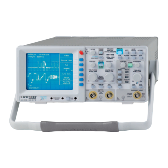
- Page 1 ® 1 0 0 M H z C o m b i S c o p e H M 1 0 0 8 Manual English...
-
Page 2: General Information Regarding The Ce Marking
HAMEG instruments fulfi ll the regulations of the EMC directive. The conformity test made by HAMEG is based on the actual generic- and 4. RF immunity of oscilloscopes. product standards. In cases where different limit values are applicable, HAMEG applies the severer standard. -
Page 3: Table Of Contents
C o n t e n t s General information regarding the CE marking AUTOSET 100 MHz CombiScope HM1008 Component tester Specifi cations CombiScope DSO Operation Important hints DSO operating modes List of symbols used: Memory resolution Positioning the instrument... - Page 4 H M 1 0 0 8 ® 1 0 0 M H z C o m b i S c o p e H M 1 0 0 8 1 GSa/s Real Time Sampling, 10 GSa/s Random Sampling Either PAL or NTSC: Line triggering with line counter 1 MPt memory per channel allows Memory up to 50,000:1...
-
Page 5: 100 Mhz Combiscope Hm1008
T e c h n i s c h e D a t e n Digital mode ® 100 MHz CombiScope HM1008 Time base range (1-2-5 sequence) Valid at 23 °C after a 30 minute warm-up period Refresh Mode: 20 ms/cm - 5 ns/cm with Peak Detect: 20 ms/cm –... -
Page 6: Important Hints
T = shipping (handle unlocked) INPUTS PUkTKl 15pF PUkTKl 15pF 400 Vp HAMEG 400 Vp PUOPFGkT PUkT C O M B I S C O P E Attention! When changing the handle position, the instrument must be placed so that it can not fall (e.g. placed on a table). -
Page 7: Environment Of Use
Statutory warranty regulations apply in the country where the II is used. Measurements on the mains are also possible if HAMEG product was purchased. In case of complaints please suitable probes like current probes are used which fulfi l the contact the dealer who supplied your HAMEG product. -
Page 8: Description Of The Controls
F r o n t P a n e l E l e m e n t s – B r i e f D e s c r i p t i o n VOLTS/DIV-SCALE-VAR (knob) Front Panel Elements – Brief Description Channel 2 Y defl... - Page 9 ANALOG ANALOG SAVE/ FOCUS INTENS POWER POWER DIGITAL MATH RECALL AUTOSET TRACE DIGITAL OSCILLOSCOPE MENU HM1008 ACQUIRE SETTINGS HELP · EXIT MENU 1 GSa 1 MB STOP REMOTE OFF 100 MHz CH 1/2 HORIZONTAL POSITION 1 POSITION 2 LEVEL A/B...
-
Page 10: Basic Signal Measurement
Values of a sine wave signal The oscilloscope HM1008 can display all repetitive signals with a fundamental repetition frequency of at least 100 MHz. The frequency response is 0 to 100 MHz (-3 dB). The vertical amplifi... -
Page 11: Dc And Ac Components Of An Input Signal
DC and ac components of an input signal is the rise time seen, t is the scope’s own rise time (3.5 ns with the HM1008), t is the rise time of the probe, e.g. voltage 2 ns. If the signal’s rise time is > 34 ns, the rise times of scope and probe may be neglected. -
Page 12: First Time Operation And Initial Adjustments
Nonsinusoidal signals require impedance matching, at both ends preferably. At the scope input a feed through – 50 Ω-ter- mination will be required. HAMEG offers a HZ22 termination. If Prior to fi rst time operation the connection between the instru-... -
Page 13: Mhz Adjustment
The HAMEG probes feature additional adjustments in the compensation box which allow to optimise their hf behaviour. -
Page 14: Xy Operation
O p e r a t i n g m o d e s o f t h e v e r t i c a l a m p l i f i e r may result as the input range of one or both amplifi ers may Please note: sin ϕ... -
Page 15: Measurement Of Amplitude Modulation
T r i g g e r i n g a n d t i m e b a s e Very small phase differences with moderately high frequencies Set the scope controls as follows in order to display the picture may yield better results with Lissajous fi... -
Page 16: Normal Trigger Mode (See Menu Mode)
T r i g g e r i n g a n d t i m e b a s e without any input signal. Thus there is always a visible trace in negative portion of a signal. This is valid in automatic and analog mode, and in DSO mode the trace will also be shown. -
Page 17: Frame Sync Pulse Triggering
T r i g g e r i n g a n d t i m e b a s e Frame sync pulse triggering Alternate trigger Remark: This mode is selected with SOURCE > Alt. 1/2. The read- Using frame sync triggering in dual trace chopped mode may out will display Tr:alt, but no more the trigger point symbol result in interference, then the dual trace alternate mode indicating level and time position. -
Page 18: Time Base B (2Nd Time Base). Delaying, Delayed Sweep. Analog Mode
T r i g g e r i n g a n d t i m e b a s e internal switching, so the next start is delayed for the so called be defl ected vertically by the input signal. In fact the input signal hold-off time, irrespective of the presence of triggers. -
Page 19: Autoset
C o m p o n e n t T e s t e r AUTOSET Component Tester For specific information consult ”Controls and Readout“ Specifi c information can be found in ”Controls and Readout“ un- AUTOSET der COMPONENT/PROBE and COMPONENT TESTER The following description is valid for both analog and DSO The scope has a built-in component tester. - Page 20 C o m p o n e n t T e s t e r Vp with bipolar transistors will suffi ce mostly as usual defects will show up. The best method to verify whether a component is defective is the comparison to a good one.
-
Page 21: Combiscope
1 or 2 points per centimeter; in other words: HAMEG oscilloscopes are either analog or they are CombiSco- the useful signal frequency is only 1/10 to 1/20 at best. -
Page 22: Dso Operation
Signals with a repetition rate lower than the rep rate of the automatic triggering can not properly trigger so the The foregoing explains why it is HAMEG policy to offer Combi- resulting display will be untriggered. Scopes rather than pure DSOs which combine the best of both... -
Page 23: Memory Depth
D a t a t r a n s f e r Memory depth apparently untriggered changing displays, or may look like AM modulated signals. If an alias is suspected change the signal 1 GS/s means that one million samples will be taken of the signal frequency or the time base or both. -
Page 24: Ho710: Rs-232 Interface. Remote Control
If the safety rules are disregarded any damage to HAMEG products will void the warranty. Neither will HAMEG take any responsibility for damages to people or gear of other make. -
Page 25: General Information Concerning Menu
G e n e r a l i n f o r m a t i o n c o n c e r n i n g M E N U POWER POWER Pushbutton CH I MENU Menu Title AC/DC/50 Ω... -
Page 26: Controls And Readout
Zoom Int. Intensity of the signal as displayed by ZOOM After turning the scope on and after the warm-up time of the (digital mode only) crt heater has elapsed the HAMEG logo, the instrument type RO-Int.: Readout intensity and the version number are displayed. If prior to switching off... -
Page 27: Analog/Digital (Pushbutton Switch)
C o n t r o l s a n d R e a d o u t 4.2 Under remote control this pushbutton will be illuminated. All entries and settings will be automatically stored upon leaving After pressing the pushbutton, control is returned to the front the Mathematics menu or turning the scope off. -
Page 28: Acquire (Pushbutton Switch)
SAVE/ FOCUS INTENS POWER POWER DIGITAL MATH RECALL AUTOSET TRACE DIGITAL OSCILLOSCOPE MENU HM1008 ACQUIRE SETTINGS HELP · EXIT MENU 1 GSa 1 MB STOP REMOTE OFF 100 MHz 7.2.5 Edit > Constant Edit Please note: In the CW position of the INTENS knob... -
Page 29: Save/Recall (Pushbutton Switch)
C o n t r o l s a n d R e a d o u t an inadvertent entering of this mode the operation of any control 9.1 Analog and DSO modes will automatically cause this mode to be reset. Under ”Save/Recall“... -
Page 30: Settings (Pushbutton Switch)
AUTOSET. During the display of HELP texts AUTOSET is not 10.2.3 Quick Start On Off available. In off the HAMEG logo, the type and the version number will not HELP be shown, the instrument will be ready immediately. 10.2.4 Menu Off time... -
Page 31: Position 2 (Knob)
C o n t r o l s a n d R e a d o u t ber of memory location, select with INTENS) > On (with or select ”Cursors“ or ”Cur. Track“. The push-button will light without associated settings). up in blue. -
Page 32: Ch 1/2-Cursor-Ch3/4-Ma/Ref-Zoom (Pushbutton)
POWER C o n t r o l s a n d R e a d o u t CH 1/2 HORIZONTAL POSITION 1 POSITION 2 LEVEL A/B X-POS CURSOR MA/REF DELAY ZOOM TRIGGER MODE TRIG ’d VOLTS / DIV VOLTS / DIV TIME / DIV ·... -
Page 33: Auto / Cursor Measure (Pushbutton Switch)
C o n t r o l s a n d R e a d o u t AUTO/CURSOR MEASURE pushbutton 18.1.4 Respect It may be necessary to determine for which signal resp. channel Pressing this pushbutton will open the menu ”Measurement“ the CURSOR measurement shall be valid. -
Page 34: Level A/B Knob
POWER C o n t r o l s a n d R e a d o u t CH 1/2 HORIZONTAL POSITION 1 POSITION 2 LEVEL A/B X-POS CURSOR MA/REF DELAY ZOOM TRIGGER MODE TRIG ’d VOLTS / DIV VOLTS / DIV TIME / DIV ·... -
Page 35: Filter (Pushbutton Switch)
C o n t r o l s a n d R e a d o u t any level can be set. If the trigger level is set such that no trig- – Noise Reject: Noise rejection (reduction) means a reduced gers are generated the automatic triggering will nevertheless trigger amplifi... -
Page 36: Trig'd (Led)
POWER C o n t r o l s a n d R e a d o u t CH 1/2 HORIZONTAL POSITION 1 POSITION 2 LEVEL A/B X-POS CURSOR MA/REF DELAY ZOOM TRIGGER MODE TRIG ’d VOLTS / DIV VOLTS / DIV TIME / DIV ·... -
Page 37: Horizontal Knob
C o n t r o l s a n d R e a d o u t intensifi ed sector is no longer visible, but the DELAY function 28.1.2 Time base B time/cm selection still can be used. This function is active if in the ”Time base“ menu (HOR push-button) SEARCH or B ONLY was selected and the option Without activated B Trigger function, the B time base will be ”B variable On Off“... -
Page 38: Hor / Var (Pushbutton Switch)
POWER C o n t r o l s a n d R e a d o u t CH 1/2 HORIZONTAL POSITION 1 POSITION 2 LEVEL A/B X-POS CURSOR MA/REF DELAY ZOOM TRIGGER MODE TRIG ’d VOLTS / DIV VOLTS / DIV TIME / DIV ·... -
Page 39: Ch1 (Pushbutton Switch)
X-POS DELAY is illuminated which means ”Delay“. The If Auto is selected HAMEG probes with automatic probe iden- length of the intensifi ed sector is determined by the speed of tifi cation connectors will be recognized by the scope and the the Z time base. - Page 40 POWER C o n t r o l s a n d R e a d o u t CH 1/2 HORIZONTAL POSITION 1 POSITION 2 LEVEL A/B X-POS CURSOR MA/REF DELAY ZOOM TRIGGER MODE TRIG ’d VOLTS / DIV VOLTS / DIV TIME / DIV ·...
-
Page 41: Ch2 (Pushbutton Switch)
CH2 pushbutton 33.4.2 auto This pushbutton opens the CH2 menu which offers the following If ”auto“ was selected HAMEG probes with special probe iden- options: tifi cation connectors will be automatically identifi ed and the appropriate factor taken into account. The probe factor identifi ed 33.1 AC DC... - Page 42 C o n t r o l s a n d R e a d o u t CH 1 VERT/XY CH 2 INPUTS AUXILIARY INPUT X-INP 1MΩII15pF TRIGGER 1MΩ II 400 Vp EXTERN 15pF Z-INPUT 100 Vp CAT I CAT I AUX pushbutton PROBE ADJ.
- Page 43 C o n t r o l s a n d R e a d o u t Subject to change without notice...
- Page 44 . h a m e g . c o m Subject to change without notice 41-1008-00E1 / 15-03-2007-gw HAMEG Instruments GmbH © HAMEG Instruments GmbH Industriestraße 6 A Rohde & Schwarz company D-63533 Mainhausen ® registered trademark Tel +49 (0) 61 82 800-0 DQS-Certifi...
Need help?
Do you have a question about the HM1008 and is the answer not in the manual?
Questions and answers