
Subscribe to Our Youtube Channel
Related Manuals for Hameg HMO Series


Summary of Contents for Hameg HMO Series
- Page 1 7 0 . . . 2 0 0 M H z D i g i t a l O s c i l l o s c o p e H M O S e r i e s 7 2 x . . . 2 0 2 x Manual English...
-
Page 2: General Information Regarding The Ce Marking
Industriestraße 6 conditions regarding emission and immunity should be observed: Fabricant D-63533 Mainhausen Die HAMEG Instruments GmbH bescheinigt die Konformität für das 1. Data cables Produkt For the connection between instrument interfaces and external devices, The HAMEG Instruments GmbH declares conformity of the product (computer, printer etc.) sufficiently screened cables must be used. -
Page 3: Table Of Contents
C o n t e n t General information regarding the CE marking Display of signals Display settings Digital Oscilloscope HMO Series 72x...202x Use of the virtual screen area Signal intensity and persistence functions Specifications 7.4 XY display Measurements Installation and safety instructions... -
Page 4: Digital Oscilloscope Hmo Series 72X
R Automatic Search for User defined Events R Pass/Fail Test based on Masks R Vertical Sensitivity 1 m V/div., Offset Control ±0.2...±20 V R 1 2 d iv. x-Axis Display Range, 20 d iv. y-Axis Display Range (VirtualScreen) R Trigger Modes: Slope, Video, Pulsewidth, Logic, Delayed, Event 0.2 Digital Oscilloscope HMO Series 72x...202x 8 Channel Logic Probe HO3508 R C omponent Tester, 6 Digit Counter, Automeasurement: max. 6 Parameters incl. Statistic, Formula Editor, Ratiocursor, FFT: 64 k Pts R Fan: Silence redefined... -
Page 5: Specifications
S p e c i f i c a t i o n s Logic: AND, OR, TRUE, FALSE 200 MHz 2 [4] Channel Digital Oscilloscope Sources LCH 0…7, CH 1, CH 2 [CH 1...CH 4] HMO2022 [HMO2024] State LCH 0…7 X, H, L Firmware: ≥ 4.522 Duration 8 ns…2.147 s, resolution 8 ns All data valid at 23 °C after 30 minutes warm-up. -
Page 6: Input Impedance
HZO20 High voltage probe 1,000:1 (400 MHz, 1,000 V Most of the specifications of the HMO series 72x ... 202x are identical. Please find the most important differences at the HZO30 Active probe 1 GHz (0.9 pF, 1 MΩ, including many accessories) following table. -
Page 7: Installation And Safety Instructions
I n s t a l l a t i o n a n d s a f e t y i n s t r u c t i o n s oscilloscope may only be operated from mains outlets with a 1 Installation and safety instructions safety ground connector. -
Page 8: Maintenance
Only valid in EU countries In order to speed claims, customers in EU countries may also Measurements in the interior of buildings (power distribution contact HAMEG directly. Also, after the warranty expired, the installations, mains outlets, motors which are permanently HAMEG service will be at your disposal for any repairs. installed). Return material authorization (RMA): Measurement CAT II: Prior to returning an instrument to HAMEG, ask for a RMA Measurements in circuits directly connected to the mains number either by internet (http://www.hameg.com) or fax... - Page 9 I n s t a l l a t i o n a n d s a f e t y i n s t r u c t i o n s fire and/or serious personal injury, and, in some cases, death. Batteries and rechargeable batteries with alkaline electrolytes (e.g.
-
Page 10: Familiarize Yourself With Your New Hmo
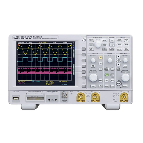
F a m i l i a r i z e y o u r s e l f w i t h y o u r n e w H M O 51 50 Fig. 2.1: Frontview of the HMO2024 15 16 2 Familiarize yourself with your new HMO Front view... -
Page 11: Screen
F a m i l i a r i z e y o u r s e l f w i t h y o u r n e w H M O Area In the area VERTICAL you find all controls of the analog channels such as the position control knob , the XY or component tester... -
Page 12: Options
The HMO series yields a DVI signal with VGA resolution panel. Connecting an 8-channel logic probe HO3508 equips (640x480). This design enables connectivity with all standard TFT the scope with 8 logic channels. -
Page 13: Basic Settings And Integrated Help
F a m i l i a r i z e y o u r s e l f w i t h y o u r n e w H M O – If a channel is deactivated, pushing the respective channel – MENU OFF (choose manual or automatic with time limit of key will switch it on. -
Page 14: Bus Signal Source
The HMO series features 4 contacts left of the channel 1 which then should you activate the updating by pushing the soft key provide the following signals according to the respective settings: EXECUTE. If you intend to update the language (including the help) or add a language choose Language in the updating menu. -
Page 15: Self Alignment
If an error occurs during the self alignment al- though it has been carried out as described, please send the exported .log file (see Self Alignment menu) to support@hameg.com. You can save the .log file to a USB stick. Fig. 2.15: Manual licence key input. -
Page 16: Quick Introduction
F a m i l i a r i z e y o u r s e l f w i t h y o u r n e w H M O To start the self alignment for the logic probe, it is necessary that 3 A quick introduction the logic probe type HO3508 is connected to the HMO. -
Page 17: Display Of Signal Details
A q u i c k i n t r o d u c t i o n On the right hand side of the screen you will see a short menu of You see now a two-window display: the display will show in channel 1, the soft keys allow you to select frequently used settings. -
Page 18: Automatic Measurements
A q u i c k i n t r o d u c t i o n Automatic measurements parameter measurement using this menu. After switching on the MEASUREMENTS with the appropriate softkey’s the parame- In addition to cursor measurements the most important signal ter measurements are displayed below the grid. -
Page 19: Storing Data
A q u i c k i n t r o d u c t i o n addition or subtraction of two activated sources. The formula editor allows to predefine 5 possible mathematical functions, it is called by pressing the MATH key (which lights up red) and the MENU key Fig. -
Page 20: Vertical System
POSITION LEVEL POSITION A q u i c k i n t r o d u c t i o n must be done manually in the channel menu. The HMO152x 4 Vertical system and HMO202x are delivered with the HZO10 a 10:1 probe with automatic attenuation read out, which will be read from the probe and factored in. -
Page 21: Bandwidth Limit And Signal Inversion
V e r t i c a l s y s t e m can be added to the signal. In order to switch this offset in the or enter a complete new name using up to 8 characters. This respective soft key must be pushed. -
Page 22: Horizontal System (Time Base)
V e r t i c a l s y s t e m 5.3.2 Roll: 5 Horizontal System (Time Base) This acquisition mode is intended specifically for very slow signals, with the untriggered signal „rolling“ across the screen from right to left (requires signals slower than 200 kHz). The As well as time base settings, the horizontal system comprises HMO uses a ring buffer to store the signal values in roll mode. - Page 23 H o r i z o n t a l S y s t e m will display on the screen. With peak detection activated when The HMO oscilloscope displays a signal window of 600x400 reading out, skipped data will be used to create a minimum and pixels (Yt without zoom). This translates into 600 data points maximum value. The smallest detectable pulse is the period of per detection. When peak detection is activated, 600 pairs the sampling rate used to write to the acquisition memory.
-
Page 24: Interlace Mode
H o r i z o n t a l S y s t e m can only be attained by means of low memory depth (as is the case with other manufacturers) it is nearly impossible to zoom in retrospectively in STOP mode. The last menu INTERPOLATION allow the selection of Sinx/x, linear or Sample-Hold as interpolation type for displaying the aquired data points. -
Page 25: Zoom Function
ZOOM function These values apply to a specified axis and can therefore also be scaled in ROLL mode. The HMO series features a memory depth of 2 MB per chan- nel. This allows the user to record long and complex signals Navigation Function which can be analyzed in full detail with the Zoom function. To activate this feature, press the ZOOM key . - Page 26 H o r i z o n t a l S y s t e m tion mode that match the manually specified search criteria. Once you have selected the appropriate search type, you can Specific settings are available for each search type. Searches choose the desired SOURCE (choose from any of the activated can be performed on any analog channel or mathematical analog channels including mathematical channels). Use the signal.
-
Page 27: Trigger System
T r i g g e r S y s t e m the signal will cause a single capture, the oscilloscope then 6 Trigger System goes into the STOP mode, indicated by the RUN/STOP key lighting up in red. The trigger system of the HMO is Trigger sources easy to handle by just observing the concept of instrument operation. -
Page 28: Pulse Trigger
T r i g g e r S y s t e m 100 MHz will improve the noise performance for the trig- the SOURCE menu that matches the properties set in the FILTER ger amplifier. This filter removes high frequencies and menu. If a pulse fulfills the trigger conditions, the oscilloscope is available with AC and DC coupling. triggers on the trailing slope, i.e. for a positive pulse it triggers on the falling slope and for a negative pulse on a rising slope. -
Page 29: Video Trigger
T r i g g e r S y s t e m TYPE key will switch the trigger source to the digital inputs. By the same procedure as with pulse trigger the reference time Pressing the SOURCE key after selecting this trigger type is adjusted with ti ≠... -
Page 30: 7 Display Of Signals
T r i g g e r S y s t e m selects all lines i.e. even when other trigger conditions are met, 7 Display of signals the oscilloscope will trigger on each line. If FRAME is selected for frame triggering, the lower menu items will allow to trigger on ODD or only EVEN half frames. In this case, the oscilloscope will trigger on the start of the half frames in the video signal. -
Page 31: 7.2 Use Of The Virtual Screen Area
This mode can be selected in The HMO series features a key that allows you to switch directly the soft menu which will open upon pushing the key INTENS/ to the XY display. Two signals will be displayed simultaneously,... - Page 32 D i s p l a y o f s i g n a l s pressing the XY key in the VERTICAL section of the control the analog channels as source for the Z input. Use the univer- panel. The key will be illuminated and the display will divided sal knob to select the desired setting.
-
Page 33: 8 Measurements
M e a s u r e m e n t s TIME 8 Measurements This mode provides 2 cursors in order to measure 3 different times and an equivalent frequency. The values t and t represent the times between the trigger and the position of the cursors. Δt represents the time between the cursors. -
Page 34: 8.2 Auto Measurements
Auto measurements PEAK – : The HMO series features cursor measurements and also This mode measures the minimum voltage value in the displayed various automatic measurements. These may be activated by view of the screen. The measurement will only be applied to the... - Page 35 M e a s u r e m e n t s PULSE WIDTH –: to the signal period of the measurement source. This mode This mode measures the width of the negative pulse. A negative searches for the slope of the measurement source that is pulse consists of a falling slope followed by a rising slope.
-
Page 36: 9 Analysis
The key RESET STATISTIC resets the statistics. All recorded values are erased. This function can be used to restart the statistics at a defined point. The key CLEAR MEASUREMENTS The HMO series oscilloscopes features an analysis function for deactivates the automatic measurements. the collected data records which are displayed on the screen. - Page 37 A n a l y s i s multiplication (MUL) or division (DIV). Pressing the MENU key in the VERTICAL control panel will switch you to a more detailed display of the QM menu. You can use the universal knob to select operands and operators. Fig. 9.4: Entry of constants and units The HMO series includes five mathematical formula sets. Each of these formula sets contains five formulas which may be edited with a formula editor to also define linked mathematical func-...
-
Page 38: 9.2 Frequency Analysis (Fft)
The new input data points when calculating the FFT. The HMO series allows you is captured, displayed and overwrites previously stored and to include up to 65k point in the FFT resulting in a very high displayed values. -
Page 39: 9.3 Quick View
A n a l y s i s man window function allows you to measure the amplitudes with high accuracy. However, it is more difficult to determine the frequency due to the wide spectral lines. This function is useful for a precise amplitude measurement of a period signal, for instance. Square wave The square wave window function multiplies all points by 1. - Page 40 A n a l y s i s and to select an action. To generate a new mask, press the soft On the right below the display window you can view the total menu key NEW MASK. Masks are displayed as light gray curves/ number and the total duration of the tests (in brackets) in white. waveforms on the screen. If a mask was copied or loaded, you The number of successful tests and their percentage (in brack- can use menu items to change the expansion of the signal form...
-
Page 41: 10 Documentation, Storing And Recalling
D o c u m e n t a t i o n , s t o r i n g a n d r e c a l l i n g You can use the soft menu key COMMENT to enter a comment 10 Documentation, storing and recalling which will be displayed in the file manager footer once a file has been selected. -
Page 42: References
D o c u m e n t a t i o n , s t o r i n g a n d r e c a l l i n g To import or export instrument settings, you must To load a reference from a USB stick or the internal memory, have a USB stick connected, otherwise the menu open the soft menu LOAD. -
Page 43: Screenshots
– = Portable Network Graphic 1.000E-02,1.000E-02,1.000E-02,1.000E-02,3.000E-02 HRT (HAMEG Reference Time) Press the soft menu key COLOR MODE to to choose from Files with this extension are reference curves of the time do- GRAYSCALE, COLOR or INVERTED with the universal knob. -
Page 44: 11 Component Test
D o c u m e n t a t i o n , s t o r i n g a n d r e c a l l i n g described in previous chapters, you must first select the 11 Component test corresponding settings for storage location, name etc. The soft menu key FILE/PRINT in the SAVE/RECALL main menu... -
Page 45: In-Circuit Tests
C o m p o n e n t t e s t With semiconductors the transition from the non-conducting (service), comparisons with intact circuits may help again. to the conducting state will be indicated in their characteristic. This is also quickly done because the intact circuit has not to As far as is possible with the available voltages and currents be functional, also it should not be energized. Just probe the the forward and backward characteristics are displayed... -
Page 46: Mixed Signal Operation (Optional)
D0 to D7. The 12 Mixed Signal Operation (optional) name is displayed to the right of the logic channels. All HMO series instruments are provided with the connector for the HO3508 logic probe necessary to add 8 digital logic channels. The firmware required for Mixed Signal operation is already contained in each HMO, only the HO3508 active logic probe need to be bought and connected. With the 4-channel... -
Page 47: Cursor Measurements For The Logic Channels
M i x e d S i g n a l O p e r a t i o n The soft menu DISPLAY SETUP opens a menu to select the TIME: display format and its extent. The universal knob in the submenu The time position of both cursors relative to the trigger time allows you to choose the format to decode the bus values. You position will be indicated;... -
Page 48: Serial Bus Analysis (Optional)
S e r i a l b u s a n a l y s i s 13 Serial bus analysis (optional) The HMO series can be equipped with three options to trigger and decode serial buses. The option HOO10 can be used to trigger and decode I... -
Page 49: Parallel Bus
Pos in the BUS short menu. 13.2 Parallel BUS The HMO series is able to analyze up to 7 bit lines. The soft menu key BUS WIDTH and the universal knob allow you to select the number of bit lines. You can use the soft menu keys PREV. BIT and NEXT BIT (or the universal knob) to move the position of the SOURCE selection bar for individual BUS bits. - Page 50 S e r i a l b u s a n a l y s i s 13.3.1 I C BUS Configuration are selected with the table display, the respective sections will also be displayed in color. These are described as follows: Prior to the BUS configuration it is necessary to set the correct logic level for the digital channels (see Read address: Yellow...
-
Page 51: Spi / Sspi Bus
Generally, this is a bus with clock and data lines and a select line (3-wire). If only one master and one slave are present, the select line may be deleted. This type of line is also called SSPI (Simple SPI) (2-wire). The HMO series supports the following bit rates (for measure- ments without measuring object via BUS SIGNAL SOURCE): – 100 kBit/s, – 250 kBit/s and –... - Page 52 S e r i a l b u s a n a l y s i s 13.4.1 SPI / SSPI BUS Configuration Chip select high or low active (low active is the default setting) Prior to the BUS configuration it is necessary to set CLK: Data will be stored with rising or falling slope (rising the correct logic level for the digital channels (see...
-
Page 53: 13.5 Uart/Rs-232 Bus
S e r i a l b u s a n a l y s i s If you choose the binary input, the soft menu key SELECT BIT and the universal knob allow you to select which individual bits within the data are to be edited. The option STATE allows you to assign a logic state to each bit (High = H = 1, Low = L = 0 or X = don’t care). The state X defines any state. If you choose the hexadecimal input, the soft menu key VALUE and the universal... -
Page 54: Can Bus
S e r i a l b u s a n a l y s i s soft menu key USER if you wish to define customized rates via universal knob or numeric input (KEYPAD button). The IDLE TIME describes the minimum time between the stop bit of the last data and the start bit of the new data. The sole purpose of the idle time is to define the start of a transmis- sion and consequently the exact start of a frame (one or more symbols, most commonly bytes). Only this information can... - Page 55 S e r i a l b u s a n a l y s i s Make sure that a complete message of a serial pro- – DATA|READ: Trigger on read and data frames; select the tocol is always displayed on the screen to ensure correct identifier type via universal knob –...
-
Page 56: Lin Bus
S e r i a l b u s a n a l y s i s state. If you choose the hexadecimal input, the soft menu key digital channel can be connected to LIN-High or LIN-Low. You VALUE and the universal knob allow you to set the value for can select any version for the LIN standard (version 1x, version the respective byte. If the input is hexadecimal, only the entire 2x, J2602 or any) via soft menu key VERSION and universal byte can be set to X. - Page 57 S e r i a l b u s a n a l y s i s pattern includes at least one X (don’t care), it is possible to Press the MENU OFF button twice or three times to close all trigger on a value equal or not equal to the specified value. If menus, and the oscilloscope will trigger on the set data. the pattern includes only 0 or 1, it is possible to trigger on an area greater than or less than the specified value. The PAT- TERN INPUT may be binary or hexadecimal. If you choose the binary input, the soft menu key BIT and the universal knob allow you to select which individual bits within the data are to be edited.
-
Page 58: Remote Control
At the first connection Windows ™ ask for a driver. The driver you can find on the delivered CD or in the internet at www.hameg.com at the download area for the HO720/HO730. The connection can be done via the normal USB or via the virtual COM port. The description how to install the driver you can find in the HO720/730 manual. -
Page 59: 15 Appendix
A p p e n d i x Fig. 7.1: Drawing of the virtual screen area 15 Appendix and an example Fig. 7.2: Menu for setting the signal display intensities Fig. 7.3: Persistence function Fig. 7.4: Settings in the X–Y menu 15.1 List of figures Fig. -
Page 60: Glossary
A p p e n d i x LIN BUS: 56 15.2 Glossary logic channel: 29, 46, 47, 50 logic level: 46, 48, 50, 52, 53, 54, 56 logic probe: 10, 12, 15, 16, 27, 28, 46, 48 logic trigger: 21, 24, 28, 46, 49 AC coupling: 20 acquisition mode: 11, 22, 25, 30, 31 ADJ. output: 16 marker function: 22, 25 analog channel: 14, 21, 26, 46, 55 mask test: 39, 40 attenuation: 20, 21 mathematical functions: 18, 19, 36, 37 automatic measurement: 10, 34, 35, 36, 37, 39 mean value: 34, 35, 39 AUTOSET: 10, 16, 17, 27 mean voltage: 18, 34, 39 Average: 22, 24, 39 mixed-signal operation: 12 bandwidth: 2, 6, 12, 20 nibble: 53 Blackman: 39 BNC connector: 11, 12, 16 brightness: 29, 30, 31, 32 offset voltage: 21... - Page 61 A p p e n d i x termination: 20 threshold: 21, 29, 32 time base: 11, 14, 15, 17, 18, 22, 23, 24, 25, 26, 31, 38, 41, 42, 44 trigger conditions: 11, 22, 27, 28, 30, 41, 50, 52, 54, 55, 56 trigger input: 11, 27, 52 trigger level: 11, 26, 27, 29 trigger signal: 11, 27, 35 trigger source: 11, 24, 27, 29, 35 trigger type: 11, 27, 29, 30, 54 two-window display: 17 universal knob: 10, 12, 13, 15, 17, 18, 19, 21, 22, 25, 26, 28, 29, 30, 31, 32, 33, 34, 35, 37, 38, 39, 40, 41, 42, 43, 46, 47, 49, 50, 51, 52, 53, 54, 55, 56, 57 USB connector: 19 USB/Ethernet: 11 USB interface: 43, 58 USB port: 10, 11, 14, 15 USB stick: 10, 14, 15, 19, 37, 38, 40, 41, 42, 43, 48, 49 V MARKER: 33, 47 Y-Output: 12 zoom: 17, 22, 25, 48, 50, 52, 53, 55, 56 zoom function: 11, 22, 26, 48 Subject to change without notice...
- Page 62 A p p e n d i x Subject to change without notice...
- Page 63 A p p e n d i x Subject to change without notice...
- Page 64 . h a m e g . c o m w w w . h a m e g . c o m Subject to change without notice HAMEG Instruments GmbH Subject to change without notice HAMEG Instruments GmbH 43-2030-2010 (10) 21092011 Industriestraße 6 41-HMOF-7XE0 (5) 02072013 Industriestraße 6 © HAMEG Instruments GmbH...
Need help?
Do you have a question about the HMO Series and is the answer not in the manual?
Questions and answers