
Related Manuals for Hameg HMO Series


Summary of Contents for Hameg HMO Series
- Page 1 7 0 . . . 2 0 0 M H z D i g i t a l O s c i l l o s c o p e H M O S e r i e s 7 2 x . . . 2 0 2 x Manual English...
-
Page 2: General Information Regarding The Ce Marking
General information regarding the CE marking HAMEG instruments fulfill the regulations of the EMC directive. The conformity test made by HAMEG is based on the actual generic- and product standards. In cases where different limit values are applicable, HAMEG applies the severer standard. For emission the limits for KONFORMITÄTSERKLÄRUNG... -
Page 3: Table Of Contents
C o n t e n t Display of signals General information regarding the CE marking Display settings 70...200 MHz Digital Oscilloscope HMO Series Use of the virtual screen area 72x...202x Signal intensity and persistence functions XY display Specifications Measurements... -
Page 4: Mhz Digital Oscilloscope Hmo Series 72X...202X
R Vertical Sensitivity 1 m V/div., Offset Control ±0.2...±20 V R 1 2 d iv. x-Axis Display Range, 20 d iv. y-Axis Display Range (VirtualScreen) R Trigger Modes: Slope, Video, Pulsewidth, Logic, Delayed, Event R C omponent Tester, 6 Digit Counter, Automeasurement: 0.2 70...200 MHz Digital Oscilloscope HMO Series 72x...202x max. 6 Parameters incl. Statistic, Formula Editor, Ratiocursor, 8 Channel Logic Probe HO3508 FFT: 64 kPts R C risp 16.5 c m (6.5") TFT VGA Display, DVI Output... -
Page 5: Specifications
S p e c i f i c a t i o n s Logic: AND, OR, TRUE, FALSE 200 MHz 2 [4] Channel Digital Oscilloscope Sources: LCH 0…7, CH 1, CH 2 [CH 1...CH 4] State LCH 0…7 X, H, L HMO2022 [HMO2024] Duration 8 ns…8.38 ms All data valid at 23 °C after 30 minutes warm-up. -
Page 6: Installation And Safety Instructions
Power consumption: Max. 45 W, typ. 25 W [max. 55 W, typ. 35 W] Most of the technical data of the HMO series 72x ... 202x are identical. Please find the most important differences at the following Protective system: Safety class I (EN61010-1) table. -
Page 7: Correct Operation
(0) 6182 800 501). If you do not have an original shipping carton, safety ground connection. If suspected that safe operation may you may obtain one by calling the HAMEG service dept (+49 (0) not be guaranteed do not use the instrument any more and lock 6182 800 500) or by sending an email to service@hameg.com. -
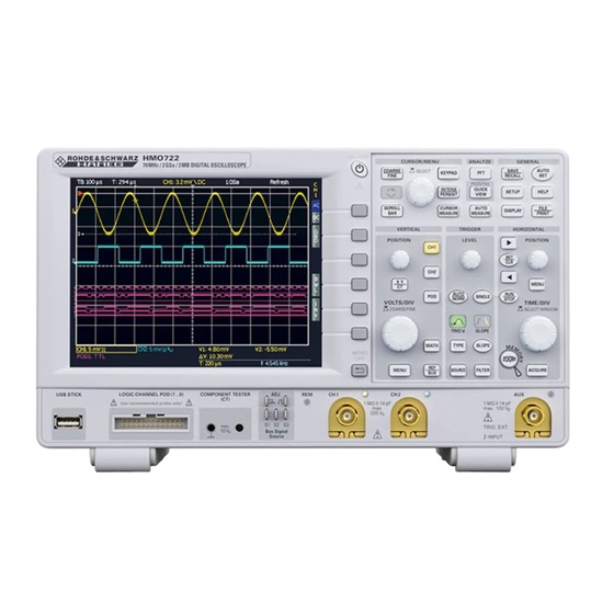
Page 8: Familiarize Yourself With Your New Hameg Digital Storage Oscilloscope
F a m i l i a r i z e y o u r s e l f w i t h y o u r n e w H M O 51 50 Fig. 2.1: Frontview of the HMO2024 2 Familiarize yourself with your new HAMEG 15 16 Digital Storage Oscilloscope... -
Page 9: Screen
On the left of the screen area little arrows [1] indicate the reference potentials of the channels. The line above the HMO series instruments offer some options which allow you graticule contains status and settings information such as the to extend the areas of application considerably. -
Page 10: General Concept Of Instrument Operation
(its LED lights up). If All HMO series instruments are prepared for mixed-signal a channel is already selected, pushing its lighted key will operation and have the appropriate connectors on the front deactivate the channel and select the next channel according panel. -
Page 11: Bus Signal Source
HELP-key. The backlight of the key and the text window will be switched off. Bus Signal Source The HMO series features 4 contacts left of the channel 1 which provide the following signals according to the respective settings: –... -
Page 12: Upgrade With Software Options
F a m i l i a r i z e y o u r s e l f w i t h y o u r n e w H M O ter selecting this menu item a window will open which displays the actual firmware version indicating the version number, the date and build information. -
Page 13: A Quick Introduction
The following chapter is intended to introduce you to the most ture (switched on for at least 20 min) and all inputs important functions and settings of your new HAMEG HMO must be without connection, which means all cable oscilloscope in order to allow you to use the instrument im- and probes must be removed from the inputs. -
Page 14: Display Of Signal Details
A q u i c k i n t r o d u c t i o n On the right hand side of the screen you will see a short menu of You see now a two-window display: the display will show in channel 1, the soft keys allow you to select frequently used settings. -
Page 15: Automatic Measurements
In addition to cursor measurements the most important signal ter measurements are displayed below the grid. If you press the parameters can be displayed. Your HAMEG oscilloscope offers softkey beside TYPE you can choose the parameter you want these possibilities: from the list using the general knob. -
Page 16: Storing Data
A q u i c k i n t r o d u c t i o n select one or two predefined mathematical functions. A quick Select the kind of data by pressing the respective soft key (in this setting of mathematical functions is possible by selecting the example SCREENSHOTS) in order to access the settings menu. -
Page 17: Vertical System
POSITION LEVEL POSITION V e r t i c a l s y s t e m setting must be done manually in the channel menu. The 4 Vertical system HMO152x and HMO202x are delivered with the HZO10 a 10:1 probe with automatic attenuation read out, which will be read from the probe and factored in. -
Page 18: Bandwidth Limit And Signal Inversion
V e r t i c a l s y s t e m can be added to the signal. In order to switch this offset in the choosen name or enter a complete new name using up to 8 respective soft key must be pushed. -
Page 19: Horizontal System (Time Base)
H o r i z o n t a l s y s t e m – Roll: 5 Horizontal System (Time Base) This is a mode especially useful for very slow signals: the signal „rolls“ slowly untriggered from right to left over the screen (signals must be slower than 200 kHz). -
Page 20: Zoom Function
H o r i z o n t a l s y s t e m Marker function – AUTOMATIC: This mode is the standard mode: the instrument always selects the optimum combination of capturing and sampling In order to access the marker function, press the key MENU in rates (full memory length used). -
Page 21: Trigger System
Using the arrow keys or the universal knob you can navigate between the events. The trigger system of the HMO is easy to handle by just observing the HAMEG concept of instrument operation. Fig. 6.1: Front panel control area of the trigger system... -
Page 22: Trigger Sources
T r i g g e r S y s t e m light up white. This indicates that the single trigger mode E.g. it is possible to define a source (channel) and a level of is active, the RUN/STOP key will blink. The next return of 120 mV on the rising slope of that signal and for the second the signal will cause a single capture, the oscilloscope then condition a level of 80 mV on the falling slope. -
Page 23: Video Trigger
T r i g g e r s y s t e m By selecting LOGIC trigger in the soft menu after pushing the two references (t and t ) can be set due to pressing the respective key TYPE the logic trigger will be enabled. If you now push the soft key and turning the universal knob. -
Page 24: Display Of Signals
D i s p l a y o f s i g n a l s digital channels D0 to D7, the buses, the math functions and 7 Display of signals the references. The analog channels can only use up to ±5 divisions from the center. -
Page 25: Xy Display
D i s p l a y o f s i g n a l s the lowest menu item toggles between HIGH and LOW of the will light up). Using the appropriate soft menu key of the first LED’s of all backlit keys and all other LED displays on the soft menu you can switch on the component tester mode. -
Page 26: Measurements
The most frequently used measurement method with an oscil- This mode provides 2 cursors in order to measure the minimum loscope is the cursor measurement. The HAMEG concept is and maximum values of a signal within the time span as defined oriented towards the expected results and thus provides not only by the two cursors. -
Page 27: Auto Measurements
Auto measurements selected channel and needs at least one complete period of a triggered signal. The HMO series oscilloscopes offer cursor measurements PEAK-TO-PEAK and additionally automatic measurements. By pushing the key AUTO MEASURE in the ANALYZE section of the front panel the In this mode the voltage difference between the minimum and menu will open. -
Page 28: Statistic For Automeasurements
M e a s u r e m e n t s measurement effects only one the selected channel and needs TRIGGER PER. at least one complete pulse of a triggered signal. In this mode the duration of a trigger period is measured with a hardware counter. -
Page 29: Analysis
For simple mathematical functions „Quick mathema- tics“ is provided. The formula editor allows you to create more The HMO series offers 5 sets of mathematical formulas. Each complex functions and the linking of functions. The frequency of these sets contains 5 equations which can be modified with analysis is accessible by just pushing a key. -
Page 30: Frequency Analysis (Fft)
A n a l y s i s (this is activated if the word is shown with a blue background) . After selecting the operators and the operands, press the soft menu key next to MODIFY to activate DISPLAY (if activated the word will be shown with a blue background). -
Page 31: Quickview Measurements
A n a l y s i s The information about the settings for the time display will be – Maximum voltage shown top left, the information about the Zoom and position – Mean voltage between both grids and the information about the FFT display –... -
Page 32: Documentation, Storing And Recalling
A n a l y s i s main menu. The test will be started if the soft menu key TEST 10 Documentation, storing and recalling is pressed. Below the display window the total number of tests and, in brackets, the total test time are shown in white. The number of successful tests and, in brackets, their percentage are shown in The oscilloscope allows you to store and recall all screen green. -
Page 33: References
D o c u m e n t a t i o n , s t o r i n g a n d r e c a l l i n g main instrument settings menu and select LOAD by pushing the memories (REF1 ... -
Page 34: Screenshots
SAVE/RECALL and SCREENSHOTS for opening the to „Automatic“. appropriate menu. HRT (HAMEG Reference Time): Data sets with this code contain data of curves vs. time. If a curve was stored in this format, it can be used in the reference menu. -
Page 35: Sets Of Formulas
C o m p o n e n t t e s t PLEASE NOTE: If you intend to print, stop signal 11 Component test capturing by pressing the RUN/STOP key first in order to guarantee a correct printout with complete curves. -
Page 36: In-Circuit Tests
C o m p o n e n t t e s t large resistive loss in series with the impedance of the pecially if those are fairly low impedance at 50 Hz /200Hz – capacitor or inductor. there will be mostly great differences compared to individual components. -
Page 37: Mixed Signal Operation (Optional)
MENU key in the VERTICAL area of the front panel. A menu will open, the top key allows to select B1 or B2 (the All HMO series instruments are provided with the connector activated one will have a blue background). The key below al- for the HO3508 logic probe necessary to add 8 digital logic lows to select the type of bus. -
Page 38: Auto Measurements For Logic Channel
M i x e d S i g n a l O p e r a t i o n TIME: The time position of both cursors relative to the trigger time position will be indicated; also the time difference between the two cursor positions from which the frequency is calculated. -
Page 39: Serial Bus Analysis (Optional)
S e r i a l b u s a n a l y s i s 13 Serial bus analysis (optional) The HMO can be equipped with three options to trigger and decode serial protocols. The option HOO10 can be used for triggering and decoding of I 2 C, SPI and UART/RS-232 buses on the digital inputs (Option HO3508) or the analog inputs. - Page 40 S e r i a l b u s a n a l y s i s Fig. 13.5: I C message, hexadecimal decoded. Fig. 13.3: Decode table of I C bus 13.2 I C bus (If only the HOO11 is installed, only the analog channel can be as sources selected, if the HOO10 is installed analog an logic The I C bus is a two-wire bus (clock and data) which was...
-
Page 41: Spi Bus
S e r i a l b u s a n a l y s i s 13.6 SPI bus configuration will only be available if it was defined before.) After pressing the key FILTER in the TRIGGER area all possible trigger types will be presented. -
Page 42: Spi Bus Triggering
S e r i a l b u s a n a l y s i s The soft menu key WORD SIZE is used to set the number of menu key VALUE is used to define whether the bit should be 0, 1 bits of a message, use the universal knob to select any number or X (don’t care). -
Page 43: Uart/Rs-232 Bus Triggering
S e r i a l b u s a n a l y s i s Fig. 13.14: Page 2 of the UART trigger menu. Fig. 13.12: Page 2 of the UART bus definition menu After pressing the soft menu key BIT RATE the universal to be used can be defined with the menu item NUMBER OF knob is used to select the standard symbol rates from 300 to SYMBOLS as 1, 2 or 3. -
Page 44: Can Bus Trigger
S e r i a l b u s a n a l y s i s In order to decode the CAN Bus you must chose the channel – ERROR: which is connected to the data signal. There is the possibility to At the new menu you can chose the kind of Error, STUFF BIT, connect a analog or digital channel to CAN-HIGH or CAN-LOW FORM, ACkNOWLEDGE and CRC. -
Page 45: Lin Bus Trigger
S e r i a l b u s a n a l y s i s In order to decode the LIN Bus you must chose the channel which if it was previously defined.) Then press the key FILTER in the is connected to the data signal. -
Page 46: Remote Control Via Interface
The settings of the parameter at the oscilloscope are done after selecting ETHERNET as the interface and the The HMO series is equipped with the interface card HO720, soft key PARAMETER is chosen. You can set anything including which have an RS-232 and USB connection on board as a a fix IP adress. -
Page 47: Appendix
A p p e n d i x Fig. 8.2: Menu for the automatic measurements settings 27 15 Appendix Fig. 8.3: Statistic for Automeasurements Fig. 9.1: Mathematics short menu 15.1 List of figures Fig. 9.2: Quick mathematics menu Fig. 9.3: Formula editor for a set of formulas Fig. - Page 48 A p p e n d i x andwidth: 10, 17, 19 licence key: 12, 13, 39 Base Level: 27 LINE MIN: 23 bipolar: 36 logic channel: 37, 40, 42 Blackman: 31 logic level: 23, 37, 39, 40, 41, 42, 43, 44 BNC connector: 9, 13 logic probes: 8, 9, 37 brightness: 25...
- Page 49 A p p e n d i x Screenshots: 16, 34 SDA: 11 semiconductors: 36 Sensitivity: 17 short menu: 9, 14, 15, 17, 18, 29, 33, 37, 38, 39 Signal inversion: 18 Signals: 16 signal source: 11, 13, 17 single sweep: 9 Single: 21 slope: 9, 21, 22, 27, 28, 37, 41 soft key: 8, 10, 11, 12, 14, 15, 16, 18, 19, 22, 23, 26, 34...
- Page 50 A p p e n d i x Subject to change without notice...
- Page 51 A p p e n d i x Subject to change without notice...
- Page 52 Subject to change without notice HAMEG Instruments GmbH 43-2030-2010 (10) 21092011 Industriestraße 6 41-HMOF-7XE0 (3) 10022012 Industriestraße 6 © HAMEG Instruments GmbH D-63533 Mainhausen © HAMEG Instruments GmbH D-63533 Mainhausen A Rohde & Schwarz Company Tel +49 (0) 61 82 800-0 A Rohde & Schwarz Company Tel +49 (0) 61 82 800-0 DQS-Certification: DIN EN ISO 9001:2000 Fax +49 (0) 61 82 800-100 DQS-Zertifikation: DIN EN ISO 9001:2000 Fax +49 (0) 61 82 800-100 Reg.-Nr.: 071040 QM...
Need help?
Do you have a question about the HMO Series and is the answer not in the manual?
Questions and answers