
Related Manuals for Hameg HM303-6


Summary of Contents for Hameg HM303-6
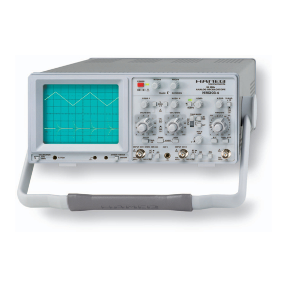
- Page 1 3 5 M H z A n a l o g O s c i l l o s c o p e H M 3 0 3 - 6 Servicemanual English Release: December, 2007...
- Page 2 HAMEG instruments fulfi ll the regulations of the EMC directive. The conformity test made by HAMEG is based on the actual generic- and 4. RF immunity of oscilloscopes. product standards. In cases where different limit values are applicable, HAMEG applies the severer standard.
-
Page 3: Table Of Contents
C o n t e n t s Analog Oscilloscope HM303-6 Specifi cations Front Panel Elements – Brief Description Short Description of HM303-6 Boards 1 YP Board 2 XY Board 3 TB Board 4 CR Board 5 CC Board 6 FC Board... - Page 4 H M 3 0 3 - 6 3 5 M H z A n a l o g O s c i l l o s c o p e H M 3 0 3 - 6 2 Channels with deflection coefficients of 1 mV/cm – 20 V/cm No signal distortion resulting from overshoot Time Base: 0.2 s/cm –...
-
Page 5: Analog Oscilloscope Hm303-6
HM303-6E/140907/ce · Subject to alterations · © HAMEG Instruments GmbH · ® Registered Trademark · DQS-certified in accordance with DIN EN ISO 9001:2000, Reg.-No.: DE-071040 QM HAMEG Instruments GmbH · Industriestr. 6 · D-63533 Mainhausen · Tel +49 (0) 6182 800 0 · Fax +49 (0) 6182 800 100 · www.hameg.com · info@hameg.com A Rohde &... -
Page 6: Specifi Cations
S p e c i f i c a t i o n s Front Panel Elements – Brief Description Element Function Element Function POWER Turns scope on and off. SLOPE / = rising edge; (pushbutton + LED) LED indicates operating (pushbutton switch) \ = falling edge. - Page 7 F r o n t P a n e l E l e m e n t s – B r i e f D e s c r i p t i o n Element Function Element Function DUAL Button released: Selects X-Y operation, one channel only.
- Page 8 B l o c k d i a g r a m Subject to change without notice...
-
Page 9: Short Description Of Hm303-6 Boards
Preliminary note: stage (IC2007). This IC also controls the trigger channel swit- This short description refers to the HM303-6 block diagram. It ches CH I, CH II (internal triggering) and external triggering contains the most important functions, but not all. -
Page 10: Tb Board
S h o r t D e s c r i p t i o n o f H M 3 0 3 - 6 B o a r d s 3 TB Board Input signals are the trigger comparator signal, the tv sync. pulses, the logic signals from sawtooth and hold off comparator 3.1 Sync. -
Page 11: Fc Board
S h o r t D e s c r i p t i o n o f H M 3 0 3 - 6 B o a r d s 5.2 COMPONENT TESTER An oscillator generates the X and Y signal components (CTX and CTY) of the component tester (CT) that can be changed by a lying electronic parts (e.g. -
Page 12: Pcb Interconnections
P C B I n t e r c o n n e c t i o n s PCB Interconnections W6002 CR-Board YP-Board J2003 W9003 W9001 W9002 FC-Board XY-Board PS-Board P4004 P4005 TB-Board CC-Board J1008 J1009 12 Subject to change without notice... - Page 13 P C B I n t e r c o n n e c t i o n s Interconnections between: YP-Board (J2006) and FC-Board (J7003) YP-Board (J2003) and XY-Board (W9005) XY-Board (P9003) and CR-Board (W6001) Direction Name Direction Name Direction Name ->...
-
Page 14: Board Replacement
B o a r d R e p l a c e m e n t Board Replacement Preliminary note! Although all PCBs have been tested by HAMEG, adjustment is required after replacement, due to unavoidable tolerances. PS Board Before removing the PS board, check that the power cable is not connected to the oscilloscope. -
Page 15: Fc Board
1 Ohm between power socket PE and rear chassis is met. with their shafts (the visible one marked “C”). 11 Connect power cable to the oscilloscope and switch it on. 12 Follow the Adjustment Procedure HM303-6 in the following order (item): 1) RV1001: Adjustment of +146 Volt supply... - Page 16 (ccw) until the unfastened hexagon sockets can be fastened. Connect power cable to the oscilloscope and switch it on. 10 Due to tolerances of the potentiometers please follow the instructions of the Adjustment Procedure HM303-6 in the following order (item): 16 Subject to change without notice...
-
Page 17: Cc Board
1) RV1001: Adjustment of +146 Volt supply Please follow the instructions of the Adjustment Procedure 2) +175 Volt check HM303-6 in the following order (item): 3) RV1003: Adjustment of +12 Volt supply 1) RV1001: Adjustment of +146 Volt supply 4) -6 Volt accuracy check... -
Page 18: Xy Board
Connect power cable to the oscilloscope and switch it on. – Please follow the instructions of the Adjustment Procedure HM303-6 and make a complete adjustment from item 1 to item 42. Press connectors “A” and pull the ribbon cables (out). -
Page 19: Tb Board
Connect power cable to the oscilloscope and switch it on. Remove the 4 screws marked “C”. Please follow the instructions of the Adjustment Procedure HM303-6 in the following order (item): Replace the TB board and follow the previous instructions 1) RV1001: Adjustment of +146 Volt supply in reverse order. -
Page 20: Cr Board
B o a r d R e p l a c e m e n t Please follow the instructions of the Adjustment Procedure HM303-6 in the following order (item): 1) RV1001: Adjustment of +146 Volt supply 2) +175 Volt check... -
Page 21: Hm303-6 Troubleshooting
H M 3 0 3 - 6 T r o u b l e s h o o t i n g HM303-6 Troubleshooting Security advice! The following procedures assume that the instrument is con- nected to mains/line via a safety class II transformer. -
Page 22: Preliminary Tests
H M 3 0 3 - 6 T r o u b l e s h o o t i n g 1.3. Set the front face of the oscilloscope on a soft surface and pull the cabinet off. (Photo 1.7, 1.8 and 1.9) Please note: After repair work, close the instrument in reverse order of above. - Page 23 H M 3 0 3 - 6 T r o u b l e s h o o t i n g 2.2 “Pump Voltage” Note: The pump voltage indicates the switch mode power Locate and identify Molex connector J1008 pin 2 (3 wires) con- supply switching frequency.
- Page 24 1 and 2 in the Adjustment Procedure. the power supply board with the CR board. See photo 2.8 – Follow the instructions of the Per formance Check HM303-6. – Disconnect the ribbon cable from J1009. – Use an Ohm meter to measure approx. 15 Ohm between wire 1 and 2 leading to pin 1 and 14 (heater) of the CRT.
-
Page 25: Error Diagnostics
H M 3 0 3 - 6 T r o u b l e s h o o t i n g 3 Error Diagnostics! The following examples will help you to determine the board to be replaced or repaired. Due to each board’s comprehensive functions it is not always possible to determine one board precisely. - Page 26 H M 3 0 3 - 6 T r o u b l e s h o o t i n g Item Behavior of the Instrument Possible Reason / What to do Remark 3-2.6 Check the power supply output voltage as described from item B1.1 to item B1.5 and continue with the following ins- tructions in that section if an error is present.
- Page 27 H M 3 0 3 - 6 T r o u b l e s h o o t i n g Item Behavior of the Instrument Possible Reason / What to do Remark 3-2.12 Locate and identify the connector J2003 on YP board. See photo 3-2.12.
- Page 28 H M 3 0 3 - 6 T r o u b l e s h o o t i n g Item Behavior of the Instrument Possible Reason / What to do Remark 3-3.1 FOCUS setting without effect. Check the voltage at the FOCUS potentiometer sliding contact (wiper) can be changed between 0 and +12 Volt.
- Page 29 H M 3 0 3 - 6 T r o u b l e s h o o t i n g Item Behavior of the Instrument Possible Reason / What to do Remark 3-5.4 Replace the TB board as described in section Board Re- placement.
- Page 30 H M 3 0 3 - 6 T r o u b l e s h o o t i n g Item Behavior of the Instrument Possible Reason / What to do Remark 3-8.2 Replace the FC board as described in section Board Re- placement.
-
Page 31: B Basic Settings
P e r f o r m a n c e C h e c k H M 3 0 3 - 6 Performance Check HM303-6 Table of Content 4) Time mark generator from 10 ns/div to 1 s/div. Output min. -
Page 32: Focus Symmetry
P e r f o r m a n c e C h e c k H M 3 0 3 - 6 3. Focus symmetry – For 0% error the signal height is 5 div. – Press X-Y pushbutton (IN position). –... -
Page 33: Ii: Y Accuracy
P e r f o r m a n c e C h e c k H M 3 0 3 - 6 5.10 CH I 1 V/div (3% accuracy) Note: – Set attenuator CH I to 1 V/div. If HZ620 is used, the minimum voltage is 10 mV without 50 Ω... -
Page 34: I: 100 Hz Square Wave
P e r f o r m a n c e C h e c k H M 3 0 3 - 6 6.7 CH II 100 mV/div (3% accuracy) 8. CH II: 100 Hz square wave – Set attenuator CH II to 100 mV/div. –... -
Page 35: Ii: Attenuator
P e r f o r m a n c e C h e c k H M 3 0 3 - 6 15.1 CH I: 2:1 Attenuator 16.2 CH II: 4:1 Attenuator – Set attenuator CH I to 10 mV/div. –... -
Page 36: I: 1 Mv/Div Y-Amplifi Er Bandwidth
P e r f o r m a n c e C h e c k H M 3 0 3 - 6 20. CH I: 1 mV/div Y-Amplifi er Bandwidth – Turn CH I VOLTS/DIV knob for a signal height of approxi- –... -
Page 37: X-Magnifi Cation X10 Linearity
P e r f o r m a n c e C h e c k H M 3 0 3 - 6 25. X-Magnifi cation x10 linearity 30. CH II: DC-Triggering – Set time base to 0.5 μs/div. – Press CH I/II pushbutton (IN position) to select channel II. -
Page 38: Spare-Part List Hm303-6
Connect a 1 kHz sine wave signal, 40 mV amplitude, to input CH I and check for full screen defl ection (80 mm at 5 mV/div). Spare-Part List HM303-6 – Set input attenuator CH I to 50 mV/div and check for 8 mm display height. -
Page 39: Adjustment Procedere Hm303-6
HAMEG companies listed on the rear cover of the manual. 8) Oscilloscope 100MHz, 5 mV/div to 5 V/div, e.g. HM 1000. -
Page 40: Before Starting Each Adjustment Procedure, Set The Oscilloscope
A d j u s t m e n t P r o c e d e r e H M 3 0 3 - 6 Table of Contents NOTE 1) RV1001: Adjustment of +146 Volt supply The adjustment procedures assume that the instrument had once been properly adjusted in the factory and adjustments are 2) +175 Volt check required due to component aging or the replacement of defective... - Page 41 A d j u s t m e n t P r o c e d e r e H M 3 0 3 - 6 RV1001: Adjustment of +146 Volt supply PS-Board 1 – Remove power supply cover. – Locate and identify RV1001 on PS-Board.
-
Page 42: Crt Minimum Intensity
A d j u s t m e n t P r o c e d e r e H M 3 0 3 - 6 -6 Volt accuracy check – Locate and identify check point socket. – Locate and identify check point socket M9001 on XY- Board. - Page 43 A d j u s t m e n t P r o c e d e r e H M 3 0 3 - 6 RV1005: Focus symmetry RV1005 PS-Board 2 – Locate and identify RV1005 on PS-Board. – Press X-Y pushbutton (IN position).
- Page 44 A d j u s t m e n t P r o c e d e r e H M 3 0 3 - 6 RV4002: Focus control Locate and identify RV4002 on TB-Board. RV4002 RV4001 TB-Board Connect a 1MHz square wave signal with 25mV at 50 Ω...
- Page 45 A d j u s t m e n t P r o c e d e r e H M 3 0 3 - 6 P2002: Y-Gain CH I at 2 mV/div P2008 P2011 P2012 – Locate and identify P2007 on YP-Board. YP-Board –...
- Page 46 A d j u s t m e n t P r o c e d e r e H M 3 0 3 - 6 P2001: 100 Hz square wave CH I P2008 P2011 P2012 – Locate and identify P2001 on YP-Board. YP-Board –...
- Page 47 A d j u s t m e n t P r o c e d e r e H M 3 0 3 - 6 C2011/C2007: 10:1 Attenuator compensation CH I P2008 P2011 P2012 – Set attenuator CH I to 5 mV/div. YP-Board –...
- Page 48 A d j u s t m e n t P r o c e d e r e H M 3 0 3 - 6 C2009/C2010: 100:1 Attenuator compensation CH I P2008 P2011 P2012 Do not adjust until the adjustment of item 15 has been made. YP-Board –...
- Page 49 A d j u s t m e n t P r o c e d e r e H M 3 0 3 - 6 P2011: Y-Gain CH II at 5 mV/div P2011 – Press CH I/II pushbutton (IN position) to select channel II. P2008 P2012 YP-Board...
-
Page 50: P2014: 100 Hz Square Wave Ch
A d j u s t m e n t P r o c e d e r e H M 3 0 3 - 6 P2016: Channel II Y-MAG. x5 balance P2008 P2011 P2012 – Press CH I/II pushbutton (IN position) to select channel II. YP-Board –... -
Page 51: P2010: Variable Balance Ch
A d j u s t m e n t P r o c e d e r e H M 3 0 3 - 6 P2010: Variable balance CH II P2008 P2011 P2012 – Press CH I/II pushbutton (IN position) to select channel II. YP-Board –... -
Page 52: C2110/C2107: 10:1 Attenuator Compensation Ch
A d j u s t m e n t P r o c e d e r e H M 3 0 3 - 6 C2110/C2107: 10:1 Attenuator compensation CH II P2008 P2011 P2012 – Press CH I/II pushbutton (IN position) to select channel II. YP-Board –... -
Page 53: C2108/C2103: 100:1 Attenuator Compensation Ch
A d j u s t m e n t P r o c e d e r e H M 3 0 3 - 6 C2108/C2103: 100 : 1 Attenuator compensation CH II P2008 P2011 P2012 Do not adjust until the adjustment of item 23 has been made. YP-Board –... - Page 54 A d j u s t m e n t P r o c e d e r e H M 3 0 3 - 6 RV4005: Sawtooth start position RV4002 RV4001 – Before measuring the sawtooth with a test oscilloscope TB-Board (e.g.
-
Page 55: Rv9004: X-Magnifi Cation X1
A d j u s t m e n t P r o c e d e r e H M 3 0 3 - 6 RV9004: X-Magnifi cation x1 – Locate and identify RV9001 RV9004 on XY-Board. RV9002 M9001 RV9003 RV9004 XY-Board... - Page 56 A d j u s t m e n t P r o c e d e r e H M 3 0 3 - 6 RV4004: 50 μs/div time base adjustment TB-Board RV4002 RV4001 – Set input attenuator CH I to 0.1 V/div. –...
-
Page 57: Rv9003: X-Magnifi Cation X10
A d j u s t m e n t P r o c e d e r e H M 3 0 3 - 6 RV9003: X-Magnifi cation x10 RV9001 – Locate and identify RV9003 on the XY-Board. RV9002 M9001 RV9003 RV9004... - Page 58 A d j u s t m e n t P r o c e d e r e H M 3 0 3 - 6 RV9002: X-Gain Adjustment in XY-Mode – Locate and identify RV9002 on XY-Board. RV9001 – Connect a 25 mV / 1 kHz square wave signal via a 50 Ω...
- Page 59 A d j u s t m e n t P r o c e d e r e H M 3 0 3 - 6 RV4001: Trigger-Symmetry – Locate and identify RV4001 on the TB-Board. TB-Board RV4002 RV4001 – Connect a 25mV , 50 kHz sine wave signal to input CH I.
-
Page 60: P2008: Dc-Triggering Ch
A d j u s t m e n t P r o c e d e r e H M 3 0 3 - 6 P2006: DC-Triggering CH I – Locate and identify P2006 on YP-Board. P2008 P2011 P2012 YP-Board –... - Page 61 A d j u s t m e n t P r o c e d e r e H M 3 0 3 - 6 CV9001/9002, RV9006/9005: Y-Final Amplifi er RV9001 – Connect a 25 mV ,1MHz square wave signal via a 50 Ω cable RV9002 M9001 RV9003...
-
Page 62: Y-Amplifi Er Bandwidth Check
A d j u s t m e n t P r o c e d e r e H M 3 0 3 - 6 38 Y-Amplifi er Bandwidth Check – Connect a 40 mV /50kHz sine wave signal from a Constant Amplitude Generator via a 50 Ω... - Page 63 A d j u s t m e n t P r o c e d e r e H M 3 0 3 - 6 40 VR7003: Trace Rotation check – Locate and identify VR7003 “TR” on front panel. –...
- Page 64 A d j u s t m e n t P r o c e d e r e H M 3 0 3 - 6 RV4502: Calibrator Output – Locate and identify RV4502 on CC-Board. CC-Board – Connect the reference lead of a multimeter to chassis and the other lead with the inner lead of the 0.2 V calibrator output socket.
-
Page 65: Invert-Balance Check Ch
A d j u s t m e n t P r o c e d e r e H M 3 0 3 - 6 45 Trigger Bandwidth Check 49 Variable-Balance Check CH I – Set time base to 0.1 μs/div, time base variable knob to CAL. –... - Page 66 Subject to change without notice HAMEG Instruments GmbH © HAMEG Instruments GmbH D-63533 Mainhausen 43-2030-2010 (5) 01042010 Industriestraße 6 A Rohde & Schwarz Company Tel +49 (0) 61 82 800-0 © HAMEG Instruments GmbH D-63533 Mainhausen DQS-Certification: DIN EN ISO 9001:2000 Fax +49 (0) 61 82 800-100 A Rohde & Schwarz Company Tel +49 (0) 61 82 800-0 Reg.-Nr.: 071040 QM sales@hameg.com DQS-Certification: DIN EN ISO 9001:2000 Fax +49 (0) 61 82 800-100 Reg.-Nr.: 071040 QM...
Need help?
Do you have a question about the HM303-6 and is the answer not in the manual?
Questions and answers