
Related Manuals for Sony HDC3100


Summary of Contents for Sony HDC3100
- Page 1 4-745-633-11 (1) Fiber Color Camera HDC3100 Triax Color Camera HDC3170 Operating Instructions Before operating the unit, please read this manual thoroughly and retain it for future reference. © 2018 Sony Corporation...
- Page 2 OPERATION Menu ............32 PAINT Menu..............40 MAINTENANCE Menu ...........43 FILE Menu..............46 DIAGNOSIS Menu ............48 Appendix ..............50 Precautions ..............50 Digital Triax Transmission (HDC3170)......50 Error Messages..............51 Using a USB Drive ........... 52 Specifications ............53 HDC3100/3170 ..............53 Optional Accessories/Related Equipment......53 Dimensions ..............55...
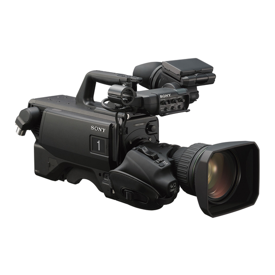
- Page 3 Overview The HDC3100/3170 are color cameras equipped with a newly developed 2/3 inch CMOS sensor with global shutter for F12 (1080/ 59.94i)/F13 (1080/50i) high sensitivity and 62 dB high signal-to-noise ratio. The HDC3100 supports operation as a studio camera when connected with an HDCU3100...
- Page 4 System Configuration Note Production of some of the peripherals and related devices shown in the figures has been discontinued. For advice on choosing devices, please contact your Sony dealer or a Sony sales representative. Connection example (optical fiber transmission) HDVF-EL75/L750/L770...
- Page 5 Connection example (digital triax) Sync signal input HDVF-EL75/L750/L770 Viewfinder Return video input HDVF-EL20 2K video Intercom HDVF-EL30 monitor microphone Viewfinder input CCA-5 Lens HDC3170 (for ENG/EFP) Triax cable RCP-1500/1000 series Remote Control Panel USB drive HDCU3170 Camera Control Unit CAC-6 VCT-14 Tripod Return Video Selector Attachment...
- Page 6 Locations and Functions of Parts k Tripod mount Accessory Attachments Attach the VCT-14 Tripod Attachment when mounting the camera on a tripod. l Camera number Insert the supplied camera number label to display the camera number. m Shoulder pad You can adjust the position so that you can get the best balance for shooting with the camera on your shoulder.
- Page 7 When the camera’s video signal is being used as output, the Controls and Connectors auto knee function may be used. The relationship between the switch setting and the output signal and auto knee function is shown in the table below. Front right OUTPUT AUTO KNEE...
- Page 8 SDI 1 (serial digital interface 1) connector (BNC-type) For 3G SDI, HD SDI or HD PROMPTER signal output. e SHUTTER switch On the HDC3100, in addition to the above signals, HD TRUNK For setting the electronic shutter functions when the camera is signal input is supported.
- Page 9 b LIGHT switch Operation panel Set to ON to illuminate the operation panel. c RET/ASSIGNABLE button A, B Press the button to switch the function assigned to the button on the <REAR FUNCTION ASSIGN> page on/off. When the return function is assigned, press the button to display the return video signal on the viewfinder screen while the button is RET/ASSIGNABLE pressed.
- Page 10 1 is output from this Note connector. To supply +12 V power, contact a Sony sales representative j TEST OUT connector (BNC-type) or Sony service representative. To output the analog signal.
- Page 11 Adjusting procedure Preparations Set the iris control to manual, and open the iris fully. Place a flange focal length adjustment chart approximately 3 meters from the camera and adjust Attaching a Lens the lighting to get an appropriate video output level. For information on handling lenses, refer to the lens’...
- Page 12 Slide the viewfinder in the direction of the arrow. Set the viewfinder front-rear positioning lever to the The viewfinder stopper automatically pops down. lock position to secure the viewfinder. Loosen the viewfinder left-right positioning ring, slide Detaching the viewfinder the viewfinder side to side to the most convenient Loosen the viewfinder left-right positioning ring, pull the position and tighten the ring.
- Page 13 1 Release the buckle, 2 bundle the cable with the Adjusting procedure belt, 3 then lock the buckle again. Shoulder pad lock lever Bottom of the camera Shoulder pad Raise the lever in the center of the shoulder pad to unlock the shoulder pad.
- Page 14 Place the camera on the tripod attachment, and slide Adjustments and forward it along the groove of the tripod attachment until it clicks. Settings for Shooting Adjusting the Black Balance and White Balance In order to maintain high picture quality, it is necessary to set the black balance and white balance appropriately for the conditions.
- Page 15 During adjustment, a message like the one in the figure below Place a white pattern in the same lighting conditions will be displayed on the viewfinder screen. as the subject, and zoom in on it so that a white area is obtained in the screen to satisfy the positional and quantitative requirements illustrated below.
- Page 16 Hunting: The automatic iris responds over and over, and the image frequency is 50 Hz, setting the shutter speed to 1/100 second repeatedly darkens and lightens. will reduce the flicker. For more information, refer to the lens’ operation manual. Selecting the shutter mode and speed When automatic white balance adjustment fails The shutter mode, and the shutter speed in standard mode, If the white balance adjustment process does not end...
- Page 17 Rotate the MENU SEL knob/ENTER button to align the To use the color detail arrow marker ( ) to “TOP” and push on the MENU Set COLOR DETAIL to ON to convert the VF detail signal SEL knob/ENTER button. to a specified color. This makes it easier to check the The TOP MENU screen is displayed.
- Page 18 You can set the display format with the menu items below. Setting the Focus Position Meter MODE: Set the type and position of the indicator. Function LEVEL: Set the density and the response speed of the indicator. The focus position meter function allows you to graphically GAIN: Set the sensitivity of the indicator.
- Page 19 INDEX COLOR: Sets the color of the index. Setting the Camera INDEX WIDTH: Sets the width of the index. MARKER WIDTH: Sets the width of the marker. Outputs To set the adjustment sensitivity and display content You can set the adjustment sensitivity and configure the display in the adjusted state using ADJUSTED SIGN on the <FOCUS POSITION METER2>...
- Page 20 To output as VBS Viewfinder Screen Status Menu page Item Setting <TEST OUT> OUTPUT Display DOWN CONVERTER SELECT Besides the video image, the viewfinder can display text and Outputting the same image as that on the messages showing the camera settings and operation status, viewfinder screen as well as items such as a center marker or safety zone •...
- Page 21 Note Menu Operations Displayed only when a serial communication lens is connected. j Battery voltage The menus displayed on the viewfinder screen enable various Displays the input voltage. settings of the camera. The following controls are used to operate the menus. k Marker name of the focus position meter Displays the marker name of the focus position meter.
- Page 22 To disable the “TOP” indication Selecting Pages Turn the power once off then on again, or set the DISPLAY switch from OFF to MENU while holding the STATUS/ CANCEL switch pressed toward CANCEL. This disables the When selecting a page from a CONTENTS TOP selection.
- Page 23 To return to the TOP MENU screen By selecting INS on the line below the character list, you Align the arrow marker ( ) with “TOP” at the top right of the can enter a space at the cursor position. menu page then press the MENU SEL knob/ENTER button.
- Page 24 For the items on each page, see the corresponding source Move the arrow marker ( ) to the item to be added menu page in the table in “Menu List” on page 27. (this operation is unnecessary if no item exists on the page, as shown in the figure for step 3) then push on The USER MENU CUSTOMIZE menu allows you to configure the MENU SEL knob/ENTER button.
- Page 25 Select MOVE then push on the MENU SEL knob/ If the CONTENTS page is displayed, turn the MENU ENTER button. SEL knob/ENTER button to move the arrow marker The previously displayed page appears again. ) to “EDIT PAGE” then push on the MENU SEL knob/ENTER button to display the EDIT PAGE screen.
- Page 26 Select “DELETE” then push on the MENU SEL knob/ ENTER button. The previously displayed page appears again, and the message “DELETE OK? YES NO” appears at the upper right. ITEM DELETE DELETE OK? 01.<VF OUT> 02.<VF DETAIL> 03.<FOCUS ASSIST> 04.<VF DISPLAY> 05.<'!' IND>...
- Page 27 Menu List This section shows the menus to be displayed on the Notes viewfinder screen in tables. CCU: HDCU3100/3170/2000/2500 Camera Control Unit • For the pages that have been registered in the USER menu Bold values (e.g. ON, OFF, 0): Default settings at the factory, the USER menu page numbers are indicated Execute via ENTER: Execute by pushing on the MENU SEL in parenthesis in the No.
- Page 28 HEADSET MIC INTERCOM CURSOR CURSOR 18 (U11) LEVEL 09 (U07) LEVEL POWER BOX/CROSS UNBAL H POSITION EARPHONE V POSITION LEVEL WIDTH INTERCOM INTERCOM RECEIVE SELECT HEIGHT BOX MEMORY PROD H POSI PGM1 V POSI PGM2 WIDTH PGM3 HEIGHT TRACKER BOX CURSOR FILE SIDETONE TRACKER TRACKER RECEIVE SELECT...
- Page 29 PAINT menu DETAIL 2 H/V RATIO SW STATUS FLARE FREQ GAMMA MIX RATIO BLK GAM KNEE APT KNEE DTL H/V MODE WHT CLIP DETAIL SKIN DETAIL SKIN DTL LVL DEP SKIN GATE SKIN DTL NATURAL SKINDTL MATRIX ZOOM LINK VIDEO LEVEL WHITE TELE BLACK...
- Page 30 MAINTENANCE menu CALL/TALLY CCU CALL AUTO SETUP AUTO BLACK CAM CALL AUTO WHITE TALLY GUARD AUTO LEVEL EXTENDER TEST FILTER DISC WHITE SHADING V SAW OUTPUT FORM CURRENT V PARA M11 (U12) H SAW TEST OUT OUTPUT H PARA M12 (U13) VBS-OUT WHITE CHARACTER...
- Page 31 FILE menu DIAGNOSIS menu READ (USB t CAM) CCU t CAM OPERATOR FILE OPTICAL LEVEL WRITE (CAM t USB) CAM t CCU PRESET CABLE LENGTH STORE PRESET FILE BOARD STATUS SCENE FILE STORE HOURS METER STANDARD ROM VERSION CAMERA APP READ (USB t CAM) D03 (U15) WRITE (CAM t USB)
- Page 32 OPERATION Menu OPERATION Page title Item Settings Description Page No. <VF DISPLAY> ON, OFF, 3S 01 (U04) ZOOM ON, OFF, 3S DISP LEFT, RIGT FOCUS ON, OFF, 3S Valid only when a serial lens is used. ON, OFF, 3S 5600K ON, OFF, 3S IRIS ON, OFF, 3S...
- Page 33 OPERATION Page title Item Settings Description Page No. <VF MARKER> MARKER ON, OFF Sets MARKER to ON/OFF. 03 (U06) WHITE, BLACK, DOT LEVEL MIN, 0 to 10, 4 CENTER ON, OFF 1, 2, 3, 4 1: Entire cross 2: Entire cross with a hole 3: Center 4: Center with a hole SAFETY ZONE...
- Page 34 OPERATION Page title Item Settings Description Page No. <FOCUS POSITION ADJUSTED SIGN METER2> SENSE 1 to 5, 2 Sets the sensitivity for the ADJUST decision. The higher the value, the higher the sensitivity. NAME DISP OFF, 1S, 3S, 5S, ON Displays/hides Marker Name, and sets the display time.
- Page 35 OPERATION Page title Item Settings Description Page No. <CURSOR> CURSOR ON, OFF 09 (U07) LEVEL WHITE, BLACK, DOT MIN, 0 to 10, 4 BOX/CROSS BOX, CROSS H POSITION 0 to 99, 50 V POSITION 0 to 99, 50 WIDTH 0 to 99, 50 HEIGHT 0 to 99, 50 BOX MEMORY...
- Page 36 OPERATION Page title Item Settings Description Page No. <VF OUT> VF OUT COLOR, Y, R, G, B 12 (U01) CHARACTER LEVEL 1 to 5, 4 PinP OFF, RETURN, HD PROMPTER Only OFF and RETURN displayed on the HDC3170. POSITION 1, 2, 3, 4 SIZE 1/2.5, 1/3, 1/4 MODE...
- Page 37 OPERATION Page title Item Settings Description Page No. <SWITCH ASSIGN2> LENS VTR S/S OFF, RETURN1 SW, RETURN2 Assigns a function to the VTR START/STOP switch SW, ENG, PROD, VTR S/S on the mounted lens. 14 (U10) FRONT RET1 OFF, RETURN1 SW, RETURN2 VTR S/S is available only when using the SW, ENG, PROD, D.EXTENDER camcorder as a stand-alone device, and adds the...
- Page 38 OPERATION Page title Item Settings Description Page No. <EXT SWITCH> RET CTRL CONNECTOR RET1 Pin5: OFF, RETURN1 SW, RETURN2 This function works when each pin of the RET CTRL SW, RETURN3 SW, ENG, PROD, connector contacts with GND (Pin3). EXTENDER, D.EXTENDER, TALLY R, G, Y are available only when using the 5600K, VF DETAIL, SPIRIT camera as a standalone device, and make the tally...
- Page 39 OPERATION Page title Item Settings Description Page No. <INTERCOM> INTERCOM RECEIVE SEPARATE, MIX SELECT ---, LEFT, RIGHT, BOTH PROD ---, LEFT, RIGHT, BOTH PGM1 ---, LEFT, RIGHT, BOTH PGM2 ---, LEFT, RIGHT, BOTH PGM3 ---, LEFT, RIGHT, BOTH TRACKER ---, LEFT, RIGHT, BOTH SIDE TONE MUTE, 1 to 99, 50 <TRACKER>...
- Page 40 PAINT Menu PAINT Page title Item Settings Description Page No. <SW STATUS> FLARE ON, OFF GAMMA ON, OFF BLK GAM ON, OFF KNEE ON, OFF WHT CLIP ON, OFF DETAIL ON, OFF LVL DEP ON, OFF SKIN DTL ON, OFF MATRIX ON, OFF <VIDEO LEVEL>...
- Page 41 PAINT Page title Item Settings Description Page No. <SATURATION> SATURATION –99 to +99, 0 ON, OFF LOW KEY SAT –99 to +99, 0 RANGE LOW, L.MID, H.MID, HIGH ON, OFF TEST OFF, SAW, 10STEP <KNEE> K POINT R/G/B/M: –99 to +99, 0 R, G, B, and M (master) values can be independently set.
- Page 42 PAINT Page title Item Settings Description Page No. <USER MATRIX> –99 to +99, 0 –99 to +99, 0 –99 to +99, 0 –99 to +99, 0 –99 to +99, 0 –99 to +99, 0 MATRIX ON, OFF PRESET ---, ON, OFF ---, SMPTE-240M, ITU-709, SMPTE-WIDE, NTSC, EBU, ITU- 601, CUSTOM1, CUSTOM2,...
- Page 43 PAINT Page title Item Settings Description Page No. <HDR OPERATION> HDR MODE OFF, LIVE HDR Displays the CCU setting. SDR GAIN 0.0 to –15 dB Enabled only when LIVE HDR is selected. Not displayed on the Gain setting applied to the SDR output. HDC3170.
- Page 44 MAINTENANCE Page title Item Settings Description Page No. <BLACK SHADING> V SAW R/G/B: –99 to +99, 0 R, G, and B values can be independently set. M (master) value can also be set for BLACK. V PARA R/G/B: –99 to +99, 0 H SAW R/G/B: –99 to +99, 0 H PARA...
- Page 45 MAINTENANCE Page title Item Settings Description Page No. <LENS2> REMOTE CONTROL OFF, ON, (OFF) Lens remote control from MSU/RCP on/off setting. Same function as the Active button on the Zoom/ Focus Control screen of the MSU/RCP. (OFF): When lens is not supported CONTROL ZOOM&FOCUS, FOCUS, ZOOM &...
- Page 46 MAINTENANCE Page title Item Settings Description Page No. <SDI OUT> SDI-1 OFF, MAIN(3G), MAIN(1.5G), MAIN(3G): Displayed only for 59.94P, 50P (when HZC-PRV50 series is installed) HD-PROMPTER M13 (U14) HD-PROMPTER: Not displayed on the HDC3170. LEVEL-A, LEVEL-B Displayed when MAIN(3G) is selected. SDI-MONI OUT MAIN, VF, RET, SD-SDI, OFF CHARACTER...
- Page 47 FILE Page title Item Settings Description Page No. <OPERATOR FILE> READ (USB t CAM) Execute via ENTER. Reads the operator file from a USB drive. WRITE (CAM t USB) Execute via ENTER. Writes the current settings of the operator file items to a USB drive.
- Page 48 FILE Page title Item Settings Description Page No. <MATRIX FILE> CUSTOM PRESET Stores and reads preset files: MATRIX When storing a preset file in camera memory, specify the file number. STORE FILE Execute via ENTER. CLEAR ALL Execute via ENTER. Clears all the files.
- Page 49 DIAGNOSIS Page title Item Indication Description Page No. <ROM VERSION> CAMERA APP Vx.xx D03 (U15) Vx.xx UPDATER Vx.xx Vx.xx Vx.xx DPRL Vx.xx OK, NG Displayed only on the HDC3170. OK, NG OK, NG <SERIAL NO.> MODEL HDCxxxx xxxxxxx EFFECTIVE FUNCTION Displayed if any option is installed.
- Page 50 White flecks Appendix Although the image sensors are produced with high-precision technologies, fine white flecks may be generated on the screen in rare cases, caused by cosmic rays, etc. This is related to the principle of image sensors and is not a malfunction.
- Page 51 Error Messages If a problem occurs during operation, a warning message is displayed. Note To display a message, set the DISPLAY switch to DISPLAY or MENU. Message Meaning TEMP WARNING The internal temperature is abnormally high. FAN STOP The built-in fan is not rotating properly.
- Page 52 • USB drives other than those recommended may not be recognized when connected to the USB connector. • USB drives must be formatted with the FAT16 or FAT32 file system. Recommended Sony USB drives are preformatted, and can be used without any prior setup.
- Page 53 USB drive) Storage temperature –20°C to +60°C (–4°F to +140°F) Supplied accessories Mass HDC3100: Approx. 4.8 kg (10 lb 9 oz) Before Using This Unit (1) HDC3170: Approx. 5.0 kg (11 lb 0.4 oz) Operating Instructions (CD-ROM) (1) Dimensions See page 55.
- Page 54 UNIT, EITHER DURING THE WARRANTY PERIOD OR AFTER EXPIRATION OF THE WARRANTY, OR FOR ANY OTHER REASON WHATSOEVER. • SONY WILL NOT BE LIABLE FOR CLAIMS OF ANY KIND MADE BY USERS OF THIS UNIT OR MADE BY THIRD PARTIES.
- Page 55 Dimensions HDC3100 Unit: mm (inches) 138 (5 363 (14 HDC3170 Unit: mm (inches) 152 (6) 363 (14...
- Page 56 On the basis of license contracts between Sony and the software copyright holders, this product uses open software. To meet the requirements of the software copyright holders, Sony is obligated to inform you of the content of these licenses. For the content of these licenses, see “License1.pdf” in the “License”...
Need help?
Do you have a question about the HDC3100 and is the answer not in the manual?
Questions and answers