Table of Contents
Advertisement
Quick Links
NOTE: Please refer to the PSD-BW Base and RTM-L Installation Instructions for complete assembly
instructions.
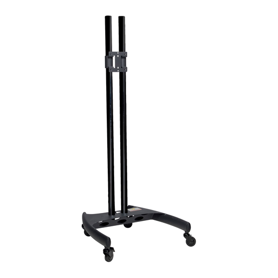
1.
Attach the support tubes to the PSD-BW base and tighten
the set screws with the supplied Allen wrench.
Landscape Orientation
Page - 1 -
9532-005-111-01
PSD-VPS
2.
Attach the RTM-L mount to the support tubes and tighten the set
screws with the supplied Allen wrench.
Portrait Orientation
Installation Instructions
PSD-VPS
Advertisement
Table of Contents

Related Manuals for Premier Mounts Nesting Cart Series


Summary of Contents for Premier Mounts Nesting Cart Series
- Page 1 PSD-VPS PSD-VPS NOTE: Please refer to the PSD-BW Base and RTM-L Installation Instructions for complete assembly instructions. Attach the support tubes to the PSD-BW base and tighten Attach the RTM-L mount to the support tubes and tighten the set the set screws with the supplied Allen wrench. screws with the supplied Allen wrench.
- Page 2 INSTALLATION MANUAL PSD-BW/PSD-BWL Nesting Cart Series AUSTRALIA,NEW ZEALAND, NORTH AMERICA EUROPE OCEANIA (Distributor) 3130 East Miraloma Avenue Swallow House, P.O. Box 295 Anaheim, CA 92806 USA Shilton Industrial Estate, Mordialloc Victoria 3195 USA and Canada – Shilton, Coventry, England CV79JY...
-
Page 3: Table Of Contents
Warranty Limited Lifetime Warranty All Premier Mounts products carry a limited lifetime warranty from ship date against defects in materials and workmanship. Premier installation that results in damage to mounts, adapters, display equipment or Mounts is not liable for improper personal injury. - Page 4 PSD-BW/L Warning Statements PREMIER MOUNTS DOES NOT WARRANT AGAINST DAMAGE CAUSED BY THE USE OF ANY PREMIER MOUNTS PRODUCT FOR PURPOSES OTHER THAN THOSE FOR WHICH IT WAS DESIGNED OR DAMAGE CAUSED BY UNAUTHORIZED ATTACHMENTS OR MODIFICATIONS, AND IS NOT...
-
Page 5: Parts List
Please verify that none of these parts are missing and/or damaged before assembly. If there are parts missing and/or damaged, please stop the assembly and contact Premier Mounts (800) 368-7000. Some mounting configurations will allow for a “landscape” orientation. In these situations, when moving the PSD- BW/L Nesting Cart through a doorway, the orientation of the display must be returned to the “portrait”... -
Page 6: Bw Base Castor Installation (Figure 1)
PSD-BW/L BW Base Castor Installation (Figure 1) Unpack the PSD-BW/L Nesting Cart and review any WARNING statements that apply to the installation. Select the desired location for the PSD-BW/L Nesting Cart. Locking Castor Non-Locking Castor Figure 1 Place the BW/L on a flat surface. Make sure the locking castors (Qty 2) are attached to the rear legs of the Nesting Cart. -
Page 7: Psd-Spa Installation (Figure 3)
PSD-BW/L PSD-SPA Installation (Figure 3) Use of the PSD-SPA will depend on the mount that is used. All PSM/CTM Series mounts require using the PSD-SPA. The Revolution Series, USA and UFA Mounts, however, do not require the use of the PSD-SPA. 1. -
Page 8: Optional Mounting Configurations
PSD-BW/L Optional Mounting Configurations CTM-Series Revolution Series USA/UFA Series Page 7 Installation Instructions... - Page 9 PSD-BW/L Technical Specifications All measurements are in inches (mm). PSD-BW PSD-BWL Notes Installation Instructions Page 8...
- Page 10 Mordialloc Victoria 3195 USA and Canada – Shilton, Coventry, England CV79JY Australia Phone: 800-368-9700 Phone: +44 (0) 2476 614700 Phone: 039586 6330 Fax: 800-832-4888 Fax: +44 (0) 2476 614710 www.premiermounts.com.au Other Locations – Phone: (001)-714-632-7100; Fax: (001)-714-632-1044 ©Premier Mounts 2008 9531-009-011-03...
- Page 11 INJURY AND PROPERTY DAMAGE. KEEP THESE INSTALLATION INSTRUCTIONS IN AN EASILY ACCESSIBLE LOCATION FOR FUTURE REFERENCE. PREMIER MOUNTS DOES NOT WARRANT AGAINST DAMAGE CAUSED BY THE USE OF ANY PREMIER MOUNTS PRODUCT FOR PURPOSES OTHER THAN THOSE FOR WHICH IT WAS DESIGNED OR DAMAGE CAUSED BY...
- Page 12 This wall mount is shipped with all proper installation hardware and components. Make sure that none of these parts are missing and/or damaged before beginning installation. If there are parts missing and/or damaged, please stop the installation and contact Premier Mounts (800-368-9700). Universal Mounting Brackets (Qty 2)
- Page 13 RTM-L (Qty 8) (Qty 8) M4 x 16 M6 x 20 (Qty 8) M4 x 25 (Qty 8) M6 x 30 (Qty 8) M5 x 12 M6 x 45 (Qty 8) (Qty 8) M5 x 16 M8 x 20 (Qty 8) (Qty 8) M5 x 20 (Qty 8)
- Page 14 RTM-L The nylon spacers may be stacked to achieve proper spacing. 9/16" Nylon spacers 1/4" Nylon spacers (large) (Qty 8) (Qty 8) 1/2" Nylon spacers Nylon sleeves (large) (Qty 8) (Qty 12) 5/16" Flat washers (metal) (Qty 8) 1" Nylon Spacers (Qty 8) 1/4"...
- Page 15 RTM-L Thread Depth Indicator 1. Insert the thread depth indicator (supplied) through the thread inserts found on the back of the fl at panel to make sure the inserts measure the same full depth and mark it (Figure 1). 2. Locate the correct diameter screw for the thread insert. Compare your marking to the screws (supplied). 3.
- Page 16 RTM-L Mount Installation The installation instructions that are contained in this manual refer only to the RTM-L. The installation instructions for the various bases that are used with the RTM-L will be included with those products. Prior to installing the RTM-L, the mounting configuration must already be assembled (base, support poles, etc.). Mounting Block Set Screws...
- Page 17 RTM-L Universal Mounting Bracket Assembly Place the universal bracket bar and the universal brackets on a flat surface. Slide the universal brackets onto the universal bracket bar (as shown below) with the set screws facing up. At this time, do not tighten the set screws that are located on the universal bracket.
- Page 18 RTM-L Lower the universal bracket bar and display into the cradle (as to the left). The circular portion of the universal brack- et bar must rest inside the nylon sleeve. If seated improperly, the operation of the RTM-S will be hindered and the nylon sleeve will become damaged.
- Page 19 RTM-L Display Orientation The RTM-L will allow the user to adjust the display a full 360°. BEFORE ROTATING THE RTM-L, MAKE SURE THAT THE M6 KNURL KNOB IS SECURELY FASTENED TO THE RTM-L. ALSO, PLEASE MAKE SURE YOU ALLOW ENOUGH CABLE AND WIRE CLEARANCE FOR FULL ROTATION.
-
Page 20: Technical Specifications
RTM-L Optional Configurations PSD-TS PSD-BW PSD-EB Technical Specifications All measurements are in inches (mm). Installation Instructions Page 11... - Page 21 RTM-L Lock-It™ Security Hardware Pack The RTM-L is shipped with a safety knurl knob already installed. If the user decides to incorporate the optional security hardware, the following steps will show the user how to effectively remove the safety knurl knob and install the optional Lock-It™ hardware kit. The M6 security head screw will be installed after the RTM-L has been fully assembled.
-
Page 22: Warranty
What Premier Mounts Will Do At the sole option of Premier Mounts, Premier Mounts will repair or replace any product or product part that is defective. If Premier Mounts chooses to replace a defective product or part, a replacement product or part will be shipped to you at no charge, but you must pay any labor costs.
Need help?
Do you have a question about the Nesting Cart Series and is the answer not in the manual?
Questions and answers