Lincoln C Series Installation And Maintenance Manual
Electronic lube meter
Hide thumbs
Also See for C Series:
- Manual (24 pages) ,
- Owner's/operator's manual (9 pages) ,
- Quick start manual (8 pages)
Table of Contents
Advertisement
Electronic lube meter
Model 905, series "C"
October 2014
Date of issue
Form number
404127H
Section
F22
Page
23H
D A N G E R
Read manual prior to installation or use
of this product. Keep manual nearby for
future reference. Failure to follow
instructions and safety precautions may
result in death or serious injury.
Installation and maintenance guide
Advertisement
Table of Contents

Related Manuals for Lincoln C Series


Summary of Contents for Lincoln C Series
- Page 1 Installation and maintenance guide Electronic lube meter Model 905, series “C” October 2014 Date of issue D A N G E R Form number 404127H Read manual prior to installation or use Section of this product. Keep manual nearby for Page future reference.
-
Page 2: Table Of Contents
Troubleshooting ........19 Lincoln industrial standard warranty ....20... -
Page 3: Safety
Please contact your This is the safety alert symbol. It is used local Lincoln distributor and refer to to alert you to potential physical injury Section K5, Page 31 for more details. -
Page 4: General
Notice W A R N I N G W A R N I N G The automatic nozzle requires Meter hazards This meter is not designed to dispense 60 psi (4,1 bar) to open and function Equipment misuse can cause the meter petroleum products or methanol based properly. - Page 5 Please contact your local Lincoln • Be sure the fluid system is properly distributor and refer to section K5, grounded. See your pump instruction page 31 for more details.
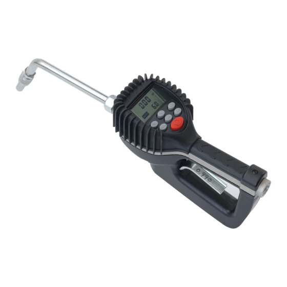
- Page 6 Meter buttons Meter display Used to enter the dispense batch quantity when in the EPM mode. Total is used to display the accumulated total of Total fluid dispensed, as well as the re-settable total Auto is used to enter and exit the manual or Auto batch mode.
-
Page 7: Meter Installation
Meter installation Flushing procedure Grounding 1 Grounding reduces the risk of static Relieve system pressure sparking. Ground all system components 1 Turn off the power supply to the pump or according to local, state, and federal close the shutoff valve. codes. -
Page 8: Apply Hose To Meter
Apply meter to hose Apply nozzle to meter Meter operation Manual mode Close the drain valve before starting this 1 On the opposite end, apply sealant to the procedure. end of the nozzle. Recommended sealant In the manual mode the meter operates as a is Loctite 243. -
Page 9: Operating Mode Functions
Operating mode Auto batch mode Notice functions To enter the batch mode from the manual In case of an emergency or to mode press the meter auto button. When in interrupt a batch, the meter is equipped the auto batch mode the auto icon displays These functions operate the same in manual with an emergency override and the batch quantity shows in the lower,... -
Page 10: Service
Service Emergency override Changing the Batteries In case of an emergency or to interrupt a The battery compartment is located in the Low battery batch, the meter is equipped with an emer- lower case on the underside of the trigger gency override. -
Page 11: Change Factory Settings
Change factory Change unit of measure Change scale factor settings Each meter is calibrated at the factory for use with motor oil († Change scale factor , page 11). The unit of measure is also se- Notice Notice lected prior to shipment. Actual unit of measure is flashing Changing scale factor changes ac- when programming mode is entered. - Page 12 Save changes 1 Push and hold at the same time the total and auto buttons. 2 The display will flash 3 times and go blank. 3 Press the reset button and the display will turn back on. Verify changes 1 Verify unit of measure is correct. 2 Push and hold the total button and auto button together, to verify that the scale factor is correct.
-
Page 13: Calcualte Scale Factor
Calculate scale factor Absolute scale factor test Notice For absolute scale factor, perform this test: Original scale factor of meter was A scale factor is a number used to adjust written on trigger when calibrated at meter accuracy. The scale factor is set at the 1 Run a measured amount of fluid through factory and may have been revised after factory using motor oil with a viscosity of... -
Page 14: Dimensions
Dimensions 11 in. (0,27 m) 3.8 in. (0,09 m) 7 in. (0,17 m) Specifications D A N G E R Maximum flow 10 gal./min. (38 l/min.) Do not use unit with flammable liquids. Minimum flow 0.25 gal./min. (1 l/min.) Operating pressure (maximum) 1,000 psi (69 bar) Operating pressure (minimum) 5 psi (0,35 bar) -
Page 15: Service Parts
Service parts Service parts Item no. Description Part number Battery holder assembly 274607 Bottom case with screws 272384 Solenoid 276319... - Page 16 Service parts, continued Service parts Item no. Description Part number Display assembly 274610 EPM2 standard register assembly 274631 Not shown Swivel, NPT 272397 Not shown Rubber boot 274609...
- Page 17 Service parts Service parts Item no. Description Part number Valve assembly 272373 Gear service kit with o-ring 272377 Trigger assembly 272378...
- Page 18 Service parts Service parts Item no. Description Part number Non-drip nozzle assembly 84799 O-ring and washer kit 272390 Nozzle assembly 272391 Consists of items 1 and 2...
-
Page 19: Troubleshooting
Troubleshooting Symptom Possible cause Remedy Battery icon is displayed Batteries are low Replace batteries Display blank Meter asleep. Push reset button. Loose battery connection. Remove battery pack and check battery connection and push reset button Batteries dead. Replace batteries and push reset button Program error Remove and reinsert battery pack. -
Page 20: Lincoln Industrial Standard Warranty
Customer service 314-679-4200 required. (international number 01-314-679-4200) In no event shall Lincoln be liable for inci- or you may also use our website dental or consequential damages. Lincoln’s www.lincolnindustrial.com liability for any claim for loss or damages... - Page 21 This page left intentionally blank...
- Page 22 This page left intentionally blank...
- Page 23 This page left intentionally blank...
- Page 24 ® SKF is a registered trademark of the SKF Group. ® Lincoln is a registered trademark of Lincoln Industrial Corp. Loctite is a registered trademark of Henkel Corporation. © SKF Group 2014 The contents of this publication are the copyright of the publisher and may not be reproduced (even extracts) unless prior written permis- sion is granted.
Need help?
Do you have a question about the C Series and is the answer not in the manual?
Questions and answers