Lincoln C Series Manual
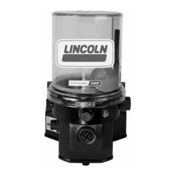
Chassis lube electric grease pump
Hide thumbs
Also See for C Series:
- Manual (24 pages) ,
- Installation and maintenance manual (24 pages) ,
- Owner's/operator's manual (9 pages)

Related Manuals for Lincoln C Series


Summary of Contents for Lincoln C Series
- Page 1 Model 94822 CHASSIS LUBE ELECTRIC GREASE PUMP Series "C" - Q3 - 14C FEB - 2006 Section FORM 403599 Page...
-
Page 2: Specifications
13.00" (330 mm) 17.72" .35" (450 mm) (9 mm) Mounting Holes 4.72" (120 mm) 9.84" 6.37" (162 mm) (250 mm) Mounting Holes 8" Figure 1 (202 mm) Do not use pump without pressu- re relief valve. SPECIFICATIONS Electrical Requirements The pump consists of a pump housing, electric gear motor, the Input 24 VDC @ 2 amps microprocessor and a plastic reservoir with stirring paddle. - Page 3 Figure 2 MOUNTING HOLE LOCATIONS Figure 3 Form 403599 Page 3...
-
Page 4: Parts List
PARTS LIST Proximity Switches ITEM DESCRIPTION QTY. PART NUMBER /KIT NUMBER The following proximity switches Reservoir 247674 for black colored blocks only: Hose 247676 Stirring paddle 544-31954-1© 234-13188-2 3-meter (9.8 ft) Control Cam 249903 cable length Bearing ring part of Kit 246434 Bearing part of Kit 246434 234-13188-3 7-meter (23.0 ft) -
Page 5: Service Parts/Kits
SERVICE PARTS/KITS Part No. Qty. Description Item No. 5050 1 Grease fitting 242125 1 Grease cap 246421 1 Housing cover 246422 1 Closure plug 246423 1 Sealing plug 246424 2 O-ring 246425 1 Intermediate plate 246426 1 Pump housing 246427 1 Eccentric cam Bearing &... - Page 6 When replacing service part 249905 microprocessor circuit board check to see that the jumpers in the new board are positioned the same as the old board. See illustration below showing location of the five jumpers. Page 6 Form 403599...
- Page 7 SYSTEM ACCESSORIES DESCRIPTION PART NO. PUSHBUTTON & LIGHT (24 VDC) 241484 8 AMP FUSE 241052 FUSE HOLDER 241053 Figure 5 Form 403599 Page 7...
- Page 8 • If the setting is modified within the pause time, the printed cir- cuit board takes over the new value only at the end of the operating time. • The pause time setting may be different for each application. It must be adjusted in accordance with the respective lubrication cycles.
- Page 9 Note: It is also possible to acknowledge any fault or to trigger an additional lubrication cycle via pushbutton 4 of the prin- ted circuit board (Fig. 14). Signal lamp • The signal lamp or the LED Figure 9 indicates the operating state of the centralized lubrication system.
-
Page 10: Time Setting
Time Setting Operational Test /To Trigger an Additional Lubrication Cycle Fig. 12 - The cover to the printed circuit board has been remo- Fig. 14 - LED of the printed circuit board * To set the pause time, remove the cover on the pump 1 - LED, left-hand 3 - LED, right-hand, housing. -
Page 11: Fault Indication
Note: The low-level signal is converted into a flashing Fault Indication signal with the a.m. frequency only after 6 motor revolutions. • In the case of a malfunction the proximity switch (initiator) can no longer record the piston movements and therefore, it cannot switch off the pump. -
Page 12: Troubleshooting
• Printed circuit board defective • Replace the printed circuit board. Americas: Europe/Africa: Asia/Pacific: © Copyright 2006 51 Changi Business Park One Lincoln Way Heinrich-Hertz-Str 2-8 Printed in USA Central 2 St. Louis, MO 63120-1578 D-69183 Walldorf #09-06 The Signature...
Need help?
Do you have a question about the C Series and is the answer not in the manual?
Questions and answers