Allen-Bradley C Series Installation Instructions Manual

Allen-Bradley C Series Installation Instructions Manual

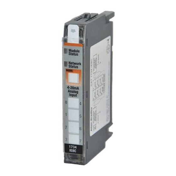
Point i/o 8 channel high density current input module

Advertisement

Installation Instructions
Original Instructions
POINT I/O 8 Channel High Density Current Input Module
Catalog Numbers 1734-IE8C, 1734-IE8CK, Series C
Catalog numbers with the suffix 'K' are conformal coated and their specifications are the same as non-conformal coated catalogs
Topic

Summary of Changes

This publication contains the following new or updated information. This list includes substantive updates only and is not intended to reflect all changes.
Topic
Page
1
4
6
6
7
9
9
10
10
11
Page
3
4, 12, 13
11
13
13
13

Advertisement

Table of Contents
loading
Need help?

Need help?

Do you have a question about the C Series and is the answer not in the manual?

Questions and answers

Summary of Contents for Allen-Bradley C Series

  • Page 1: Table Of Contents

    Installation Instructions Original Instructions POINT I/O 8 Channel High Density Current Input Module Catalog Numbers 1734-IE8C, 1734-IE8CK, Series C Catalog numbers with the suffix ‘K’ are conformal coated and their specifications are the same as non-conformal coated catalogs Topic Page Summary of Changes Before You Begin Install the Mounting Base...
  • Page 2 POINT I/O 8 Channel High Density Current Input Module Installation Instructions ATTENTION: Read this document and the documents listed in the Additional Resources section about installation, configuration and operation of this equipment before you install, configure, operate or maintain this product. Users are required to familiarize themselves with installation and wiring instructions in addition to requirements of all applicable codes, laws, and standards. Activities including installation, adjustments, putting into service, use, assembly, disassembly, and maintenance are required to be carried out by suitably trained personnel in accordance with applicable code of practice.
  • Page 3: Updated European Hazardous Location Certification

    POINT I/O 8 Channel High Density Current Input Module Installation Instructions Environment and Enclosure ATTENTION: This equipment is intended for use in a Pollution Degree 2 industrial environment, in overvoltage Category II applications (as defined in EN/IEC 60664-1), at altitudes up to 2000 m (6562 ft) without derating. This equipment is not intended for use in residential environments and may not provide adequate protection to radio communication services in such environments.
  • Page 4: Before You Begin

    POINT I/O 8 Channel High Density Current Input Module Installation Instructions WARNING: Special Conditions for Safe Use: • This equipment is not resistant to sunlight or other sources of UV radiation. • This equipment shall be mounted in an ATEX/IECEx Zone 2 certified enclosure with a minimum ingress protection rating of at least IP54 (in accordance with EN/IEC 60079-15) and used in an environment of not more than Pollution Degree 2 (as defined in EN/IEC 60664-1) when applied in Zone 2 environments.
  • Page 5 POINT I/O 8 Channel High Density Current Input Module Installation Instructions See the figures to familiarize yourself with major parts of the module, noting that the wiring base assembly is one of the following: • 1734-TB or 1734-TBS POINT I/O™ two-piece terminal base, which includes the 1734-RTB or 1734-RTBS removable terminal block, and 1734-MB mounting base •...
  • Page 6: Install The Mounting Base

    POINT I/O 8 Channel High Density Current Input Module Installation Instructions Install the Mounting Base To install the mounting base on the DIN rail (Allen-Bradley part number 199-DR1; 46277-3; EN50022), proceed as follows: ® ATTENTION: This product is grounded through the DIN rail to chassis ground. Use zinc plated chromate-passivated steel DIN rail to assure proper grounding.
  • Page 7: Install The Removable Terminal Block

    POINT I/O 8 Channel High Density Current Input Module Installation Instructions Verify that the DIN rail locking screw is in the horizontal position. You cannot insert the module if the locking mechanism is unlocked. 1734-TB Base 1734-TOP Base Be sure that the DIN rail locking screw is in the Turn the keyswitch to horizontal position.
  • Page 8 POINT I/O 8 Channel High Density Current Input Module Installation Instructions If an I/O module is installed, snap the RTB handle into place on the module. Hook the RTB end into the mounting base end, and rotate until it locks into place. WARNING: For 1734-RTBS and 1734-RTB3S, to latch and unlatch the wire, insert a bladed screwdriver (catalog number 1492-N90 –...
  • Page 9: Remove A Mounting Base

    POINT I/O 8 Channel High Density Current Input Module Installation Instructions Remove a Mounting Base To remove a mounting base, you must remove any installed module, and the module installed in the base to the right. Remove the removable terminal block, if wired. WARNING: When you insert or remove the module while backplane power is on, an electric arc can occur.
  • Page 10: Communicate With The Module

    POINT I/O 8 Channel High Density Current Input Module Installation Instructions Communicate with the Module POINT I/O modules send (consume) and receive (produce) I/O data (messages). You map this data onto the processor’s memory. This module produces 24 bytes of input data (scanner Rx) and fault status data. It does not consume I/O data (scanner Tx). Default Data Map Message size: 24 Bytes Input Channel 0 High Byte...
  • Page 11: Specifications

    POINT I/O 8 Channel High Density Current Input Module Installation Instructions Indicator Status for Module (Continued) Status Description Device is not online: — Device has not completed dup_MAC-id test. — Device not powered – check module status indicator. Flashing green Device is online but has no connections in the established state.
  • Page 12: Added Iecex Certification

    POINT I/O 8 Channel High Density Current Input Module Installation Instructions Input Specifications (Continued) Attribute Value -60 dB Notch Filter 13.1 Hz @ Notch = 50 Hz 15.7 Hz @ Notch = 60 Hz (default) 26.2 Hz @ Notch = 100 Hz Normal mode rejection ratio 31.4 Hz @ Notch = 120 Hz 52.4 Hz @ Notch = 200 Hz...
  • Page 13: Updated Radiated Rf Immunity Specification

    POINT I/O 8 Channel High Density Current Input Module Installation Instructions Environmental Specifications Attribute Value IEC 60068-2-1 (Test Ad, Operating Cold), IEC 60068-2-2 (Test Bd, Operating Dry Heat), Temperature, operating IEC 60068-2-14 (Test Nb, Operating Thermal Shock): -20…+55 °C (-4…+131 °F) Temperature, surrounding air, max 55 °C (131 °F) IEC 60068-2-1 (Test Ab, Unpackaged Nonoperating Cold),...
  • Page 14 Rockwell Otomasyon Ticaret A.Ş. Kar Plaza İş Merkezi E Blok Kat:6 34752 İçerenköy, İstanbul, Tel: +90 (216) 5698400 EEE Yönetmeliğine Uygundur Connect with us. Allen-Bradley, expanding human possibility, FactoryTalk, POINT I/O, POINTBus, Logix 5000, Rockwell Automation, RSLogix 5000, Studio 5000 Logix Designer, and TechConnect are trademarks of Rockwell Automation, Inc.

This manual is also suitable for:

1734-ie8c1734-ie8ck

Table of Contents