
Subscribe to Our Youtube Channel
Related Manuals for DEUTSCHMANN AUTOMATION UNIGATE MB - MPI


Summary of Contents for DEUTSCHMANN AUTOMATION UNIGATE MB - MPI
- Page 1 Instruction Manual Universal Fieldbus-Gateway ® UNIGATE MB - MPI Deutschmann Automation GmbH & Co. KG www.deutschmann.com | wiki.deutschmann.de...
- Page 2 Manual Art.-No.: V4046E...
-
Page 3: Table Of Contents
Deutschmann Automation GmbH & Co. KG Information on CE marking of the module ....8 EU Directive EMC ......8 Scope of application . - Page 4 Deutschmann Automation GmbH & Co. KG 8.3.1 Data structure 3964R ......21 8.3.2 Protocol definitions .
- Page 5 Deutschmann Automation GmbH & Co. KG Hardware ports, switches and LEDs ....45 Device labeling ......45 Connectors .
- Page 6 Deutschmann Automation GmbH & Co. KG 14.7 MPI-bus-connection ......58 14.8 Connection to the process device ..... 58 14.9 Connecting the supply voltage .
- Page 7 We would be pleased to receive any improvement proposals which you may have. Copyright Copyright (C) Deutschmann Automation GmbH & Co. KG 1997 – 2021. All rights reserved. This document may not be passed on nor duplicated, nor may its contents be used or disclosed unless expressly permitted.
-
Page 8: Information On Ce Marking Of The Module
The EU Declarations of Conformity are available at the following location for perusal by the responsible authorities in accordance with the EU Directive, Article 10: Deutschmann Automation GmbH & Co. KG, Carl-Zeiss-Straße 8, 65520 Bad Camberg, Ger- many. Scope of application The modules are designed for use in the industrial sector and comply with the following... -
Page 9: Information For The Machine Manufacturers
Deutschmann Automation GmbH & Co. KG Information for the machine manufacturers Information for the machine manufacturers Introduction ® The UNIGATE module does not constitute a machine as defined by the EU "Machinery“ Directive. Consequently, the module does not have a Declaration of Conformity in relation to the EU Machinery Directive. -
Page 10: Introduction
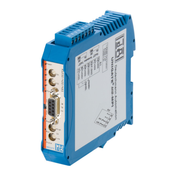
Introduction Deutschmann Automation GmbH & Co. KG Introduction ® The module UNIGATE MB-MPI serves to adapt a serial port to the Siemens MPI-bus. In this application, it functions as a Gateway and operates as MPI master or slave, optionally adjustable via Script. -
Page 11: Unigate ® Mb Software Flow-Chart
Deutschmann Automation GmbH & Co. KG Introduction ® UNIGATE MB software flow-chart ® ® 27.10.21 UNIGATE fieldbus gateway UNIGATE MB - MPI V. 1.9... -
Page 12: Unigate ® Block Diagram
Introduction Deutschmann Automation GmbH & Co. KG ® UNIGATE block diagram ® The following picture shows a typical UNIGATE -module design. ® UNIGATE application diagram The following graph shows a typical connection scheme. ® ® UNIGATE fieldbus gateway UNIGATE MB - MPI V. 1.9... -
Page 13: Operation Modes Of The Gateway
Deutschmann Automation GmbH & Co. KG Operation modes of the Gateway Operation modes of the Gateway Configuration mode (config mode) The configuration mode serves to configure the Gateway. The following adjustments are possible in this mode. • Loading a Script •... -
Page 14: Data Exchange Mode
Operation modes of the Gateway Deutschmann Automation GmbH & Co. KG In this mode the State-LED on the RS-side will be flashing red, the "Error No/Select ID" LEDs will be displaying the value in a binary way, that is issued that moment. Additionally each character that is received at one of the interfaces will also be output at the same interface as a local echo. -
Page 15: Rs-Interface
Deutschmann Automation GmbH & Co. KG RS-interface RS-interface ® RS-interfaces at the UNIGATE ® The UNIGATE MB - MPI has the interfaces RS232, RS422 and RS485 available. ® Buffer sizes at the UNIGATE ® UNIGATE MB features at the serial side a buffer with the size of 1024 bytes for input data and output data each. -
Page 16: Ssi-Interface
SSI-interface Deutschmann Automation GmbH & Co. KG SSI-interface ® The UNIGATE also supports the connection of applications or products, that communicate via SSI. Initiation of the SSI-interface The configuration of the SSI-interface is executed in the config mode with the WINGATE soft- ware, Protocol SSI. -
Page 17: Hardware-Wiring
Deutschmann Automation GmbH & Co. KG SSI-interface Hardware-wiring The clock wires of the SSI-interface are placed onto the Tx-wires of the RS422-interface and the ® data wires onto the Rx-wires at the UNIGATE X1 (3pin + 4pin screw-plug-connector): Pin no. -
Page 18: Mode Of Operation Of The System
Communication can be split into seven layers, Layer 1 to Layer 7, in accordance with the ISO/OSI model. The Deutschmann Automation Gateways convert Layers 1 and 2 of the customized bus system (RS485 / RS232 / RS422) to the corresponding Fieldbus system. Layers 3 to 6 are blank, and Layer 7 is converted in accordance with chapter 7.3. -
Page 19: Implemented Protocols In Unigate ® Mb
Deutschmann Automation GmbH & Co. KG Implemented protocols in UNIGATE® MB Implemented protocols in UNIGATE ® ® UNIGATE MB is supplied with the Script “Universal Script Deutschmann“. The configuration of the protocols is carried out in the configuration mode (see Chapter 4.1) with the software WING- ®... -
Page 20: Data Structure
Implemented protocols in UNIGATE® MB Deutschmann Automation GmbH & Co. KG 8.2.1 Data structure 8.2.2 Fieldbus parameters Trigger byte: See „The trigger byte“, chapter 8.6 Length byte: See „The length byte“, chapter 8.7 8.2.3 RS232 parameter table 8.2.3.1 Start character (232 Start character) If this character is defined, the gateway evaluates only the data at the RS232 interface following this start character. -
Page 21: Communication Sequence
Deutschmann Automation GmbH & Co. KG Implemented protocols in UNIGATE® MB 8.2.4 Communication sequence The useful data (data area) arriving via the fieldbus is copied in accordance with chapter 8.2.1 transparently into the RS232 data field and transferred via the RS interface, whereby the protocol is supplemented in accordance with the configuration (start character, end character...). -
Page 22: Conflicts
Implemented protocols in UNIGATE® MB Deutschmann Automation GmbH & Co. KG 8.3.3.2 Conflicts 8.3.3.3 Timeout times The timeout times are preset by the definition of the 3964R protocol and cannot be overwritten !!! tq = acknowledgement timeout time (2 s). -
Page 23: Data Structure
Deutschmann Automation GmbH & Co. KG Implemented protocols in UNIGATE® MB The user can choose whether the fieldbus requests are forwarded to the Modbus in case of a change (On Change) or on request (On Trigger). In "Change" mode, detection of a change is based on the fact that the fieldbus data is compared with that of the last transmission, and a request is issued by the Modbus only in the case of a change. -
Page 24: Data Structure
Implemented protocols in UNIGATE® MB Deutschmann Automation GmbH & Co. KG Since the Modbus operates with a variable data format - dependent on the required function and data length - but since the fieldbus requires a fixed data length, this must be preset by means of a selection in the device description file. -
Page 25: The Trigger Byte
Deutschmann Automation GmbH & Co. KG Implemented protocols in UNIGATE® MB The trigger byte Since the data is always transferred cyclically on PROFIBUS, the gateway must detect when the user wishes to send new data via the serial interface. This is normally done by the gateway com- paring the data to be transferred via the PROFIBUS with the old data stored internally - data exchange on change (data exchange ->... -
Page 26: Data Structure On The Fieldbus Side E.g.: Profibus
Implemented protocols in UNIGATE® MB Deutschmann Automation GmbH & Co. KG 8.8.1 Data structure on the fieldbus side e.g.: PROFIBUS Applies to In and Out 1. Byte: trigger byte, optional (see chapter 8.6, The trigger byte) 2. Byte: fieldbus length byte, optional (see chapter 8.7, The length byte) 3. -
Page 27: Example: Fc3 (Read Holding Register) + Fc4 (Read Input Register)
Deutschmann Automation GmbH & Co. KG Implemented protocols in UNIGATE® MB Display of the data in the Modbus Master (FC1): Example: StartAddress 0008, Length 80, FC2 (Read Input Status) [01] [02] [00] [07] [00] [50] [c9] [f7] ® UNIGATE sends response via RS232/485:... -
Page 28: Example: Write Single Coil Fc5
Implemented protocols in UNIGATE® MB Deutschmann Automation GmbH & Co. KG 8.8.1.3 Example: Write Single Coil FC5 ® The Fieldbus Master sent the following data to the UNIGATE once: 07 01 02 03 04 05 06 07 08 09 0A 0B 0C 0D 0E 0F 10 11 12 13 14 15 16 17 18 19 1A 20 20 20... -
Page 29: Example: Write Single Register Fc6
Deutschmann Automation GmbH & Co. KG Implemented protocols in UNIGATE® MB In the following example the Bit (Coil) in Address 0002 is set to High (1): The fieldbus data is updated: 02 03 04 05 06 07 00 00 00 00 00 The internal buffer reserves this value, which means it can be read back by the Master via FC1 Read Coil status:... -
Page 30: Example: Force Multiple Coils Fc 15
Implemented protocols in UNIGATE® MB Deutschmann Automation GmbH & Co. KG The 2nd row shows the fieldbus data AFTER the write command. You can see that the value 00 07 is send as Address in the Modbus request. (As mentioned in the chapter Universal Modbus Master some Master pull System one as offset.) -
Page 31: Protocol „Universal Modbus Rtu Master
Deutschmann Automation GmbH & Co. KG Implemented protocols in UNIGATE® MB The 1st row shows the fieldbus BEFORE the request: 1F 0E FF 03 04 05 06 07 FF 00 00 00 00 00 00 00 00 00 00 00 00 00 00 00 00 00 00 00 00 00... ... -
Page 32: Configuration: Via Wingate Since Wcf Datei Version 396
Implemented protocols in UNIGATE® MB Deutschmann Automation GmbH & Co. KG 8.9.3 Configuration: via Wingate since wcf Datei Version 396 Parameter Name value range Explanation Modbus Timeout (10ms) 1 ... 255 (10ms ... 2550ms) Max. Waiting time for the "Response" before an error 9 is generated by timeout. -
Page 33: Example: Read Coil Status Fc1
Deutschmann Automation GmbH & Co. KG Implemented protocols in UNIGATE® MB 8.9.3.1 Example: Read coil status FC1 Configuration Data content Modbus Slave ® UNIGATE reads Address 5 + 6 and copies it into the 6. byte of the output buffer.... -
Page 34: Example: Read Input Status Fc2
Implemented protocols in UNIGATE® MB Deutschmann Automation GmbH & Co. KG AD 07 00 00 00 00 00 00 01 00 00 00 00 00 00 00 AE 07 00 00 00 00 00 00 03 00 00 00 00 00 00 00... -
Page 35: Example: Read Multiple Register Fc3
Deutschmann Automation GmbH & Co. KG Implemented protocols in UNIGATE® MB Here the content of the address 10009 is changed from 0 -> 1 In the following example only the "No. Of Points" is switched to 10. Which means that now 10 Bits => 2 Byte are read out. This is also the reason why the fieldbus length byte (2. -
Page 36: Example: Read Input Registers Fc4
Implemented protocols in UNIGATE® MB Deutschmann Automation GmbH & Co. KG Thereby the addressed slave holds the following data in its registers.: register address value(hex) 40000 0x0000 40001 0x0202 40002 0x0303 40003 0x0000 40004 0x0000 register = 1 Word = 2 Byte In the documentation of some applications, an Offset + 1 at the address is assu- med. -
Page 37: Example: Preset Single Register Fc6
Deutschmann Automation GmbH & Co. KG Implemented protocols in UNIGATE® MB 8.9.3.6 Example: Preset single register FC6 Configuration ® SPS sends to UNIGATE 00 FF 00 00 00 00 00 FF 00 00 00 00 00 00 00 00 00 00 00 00 00 ... ... -
Page 38: Example: Preset Multiple Register Fc16
Implemented protocols in UNIGATE® MB Deutschmann Automation GmbH & Co. KG Storage content of Modbus Slave after response: Please keep in mind that No. Of coild = 10, hence, only the lower bit in address 0011 is written at the value 0x05. Address 0013 would already be bit No. 11, which is not transmitted anymore.... -
Page 39: Protocol „Universal Modbus Ascii Master/Slave
Deutschmann Automation GmbH & Co. KG Implemented protocols in UNIGATE® MB 8.10 Protocol „Universal Modbus ASCII Master/Slave“ ® The fieldbus data exchange for Modbus ASCII is identical with RTU. The UNIGATE automati- cally transmits the data in ASCII format on the serial side.... - Page 40 Implemented protocols in UNIGATE® MB Deutschmann Automation GmbH & Co. KG PROFIBUS Master sends and receives: ® ® UNIGATE fieldbus gateway UNIGATE MB - MPI V. 1.9 27.10.21...
-
Page 41: Swap Word
Deutschmann Automation GmbH & Co. KG Implemented protocols in UNIGATE® MB Modbus Slave storage content: 8.10.1.2 Swap Word Configuration with „Swap Word“ = enabled. Fieldbus data is swapped to the Modbus slave. Meaning High Byte and Low Byte are switched. - Page 42 Implemented protocols in UNIGATE® MB Deutschmann Automation GmbH & Co. KG The swapping is bidirectional Modbus Slave Data content ® ® UNIGATE fieldbus gateway UNIGATE MB - MPI V. 1.9 27.10.21...
-
Page 43: Example With Fast Ethernet
Deutschmann Automation GmbH & Co. KG Implemented protocols in UNIGATE® MB 8.10.1.3 Example with Fast Ethernet ® ® 27.10.21 UNIGATE fieldbus gateway UNIGATE MB - MPI V. 1.9... - Page 44 Implemented protocols in UNIGATE® MB Deutschmann Automation GmbH & Co. KG ® ® UNIGATE fieldbus gateway UNIGATE MB - MPI V. 1.9 27.10.21...
-
Page 45: Hardware Ports, Switches And Leds
Deutschmann Automation GmbH & Co. KG Hardware ports, switches and LEDs Hardware ports, switches and LEDs Device labeling Picture 1: Terminal labeling and termination Picture 2: Front panel: Rotary switches, LEDs and termination MPI In case the front panel should pop out it does not affect the device’s function or quality. -
Page 46: Connector Supply Voltage
Hardware ports, switches and LEDs Deutschmann Automation GmbH & Co. KG For the operation at a 485-interface the two pins labeled "485-" have to be connected together. Also the two pins "485+". 9.2.2 Connector supply voltage Pin assignment X2 (4-pole screw-plug connector, on the bottom side, at the back) Pin No. -
Page 47: Led "(Bus) State
Deutschmann Automation GmbH & Co. KG Hardware ports, switches and LEDs 9.3.3 LED "(Bus) State" Lights green MPI-bus in the state data exchange "Data Sync." Flashes green Gateway waits for MPI-bus-configuration data or data exchange is interrupted Flashes green/red Bus is not initialized (Script command "Bus Start" not executed) -
Page 48: Rotary Coding Switches S4 + S5 (Serial Interface)
Hardware ports, switches and LEDs Deutschmann Automation GmbH & Co. KG 9.4.2 Rotary coding switches S4 + S5 (serial interface) Via these two switches the RS485 -ID of the gateway is set to hexadecimal, as long as an ID is necessary for the bus. -
Page 49: Error Handling
Deutschmann Automation GmbH & Co. KG Error handling 10 Error handling ® 10.1 Error handling at UNIGATE If the Gateway detects an error, the error is signalled by the “State“ LED lighting red and, simulta- neously, the error number being indicated by means of LEDs “Error No.“ as shown in the table below. - Page 50 Error handling Deutschmann Automation GmbH & Co. KG Error- LED8 LED4 LED2 LED1 Protocol Error description all Protocols No Universal script support all Protocols Unknown Protocols Modbus RTU Master Timeout-Modbus Slave Modbus ASCII Master Participant didn’t response in set time frame (response time).
-
Page 51: Installation Guidelines
Deutschmann Automation GmbH & Co. KG Installation guidelines 11 Installation guidelines 11.1 Installation of the module The module with the dimensions 23 x 117 x 111 mm (W x D x H) has been developed for switch cabinet use (IP 20) and can thus be mounted only on a standard mounting channel (deep DIN-rail to EN 50022). -
Page 52: Equipotential Bonding Connection
Installation guidelines Deutschmann Automation GmbH & Co. KG 11.2.1.2 Equipotential bonding connection The connection to the potential equalization automatically takes place it is put on the DIN-rail. 11.2.2 MPI-bus communication interface 11.2.2.1 Bus line with copper cable This interface is located on the module in the form of a 9-pin D-SUB socket on the front side of the housing. -
Page 53: Shielding Of Lines
Deutschmann Automation GmbH & Co. KG Installation guidelines 11.2.4.1 Shielding of lines Shielding is intended to weaken (attenuate) magnetic, electrical or electromagnetic interference fields. Interference currents on cable shields are discharged to earth via the shielding bus which is con- nected conductively to the chassis or housing. -
Page 54: Representation Of The Data In A S7
Representation of the data in a S7 Deutschmann Automation GmbH & Co. KG 12 Representation of the data in a S7 Any MPI-device (e. g. S7 - 300) can exchange data with the Gateway. It is also possible to use very "simple"... -
Page 55: Technical Data
Deutschmann Automation GmbH & Co. KG Technical data 13 Technical data 13.1 Device data The technical data of the module is given in the table below. No. Parameter Data Explanations Location Switch cabinet DIN-rail mounting Enclosure IP20 Protection against foreign... -
Page 56: Interface Data
Technical data Deutschmann Automation GmbH & Co. KG 13.1.1 Interface data The table below lists the technical data of the interfaces and ports on the device. The data has been taken from the corresponding Standards. Interface designation MPI-bus RS232-C RS485/RS422 No. -
Page 57: Commissioning Guide
Deutschmann Automation GmbH & Co. KG Commissioning guide 14 Commissioning guide 14.1 Note ® Only trained personnel following the safety regulations may commission the UNIGATE 14.2 Components ® You will require the following components to commission the UNIGATE ® •... -
Page 58: Setting The Mpi-Address
Commissioning guide Deutschmann Automation GmbH & Co. KG 14.6 Setting the MPI-address Set the MPI-address at the fieldbus end of the module on the two rotary switches designated "High" and "Low". This adjustment is carried out in a hexadecimal way. -
Page 59: Servicing
Deutschmann Automation GmbH & Co. KG Servicing 15 Servicing Should questions arise that are not covered in this manual you can find further information in our • FAQ/Wiki area on our homepage www.deutschmann.com or directly in our Wiki on www.wiki.deutschmann.de... -
Page 60: Annex
Annex Deutschmann Automation GmbH & Co. KG 16 Annex 16.1 Explanations of the abbreviations General Product group CL (Compact Line) Product group CM (CANopen Line) Product group CX Product group EL (Ethernet Line) Product group FC (Fast Connect) Galvanic separation RS-side Housing color gray... -
Page 61: Hexadecimal Table
Deutschmann Automation GmbH & Co. KG Annex ® PBDPL ProfibusDP-version L (see comparison table UNIGATE IC for the respective product) ® PBDPX ProfibusDP-version X (see comparison table UNIGATE IC for the respective product) PBDPV0 = ProfibusDPV0 PBDPV1 = ProfibusDPV1 Serial RS232/485/422 16.2 Hexadecimal table... - Page 62 Annex Deutschmann Automation GmbH & Co. KG ® ® UNIGATE fieldbus gateway UNIGATE MB - MPI V. 1.9 27.10.21...
- Page 63 Deutschmann Automation GmbH & Co. KG Annex ® ® 27.10.21 UNIGATE fieldbus gateway UNIGATE MB - MPI V. 1.9...
Need help?
Do you have a question about the UNIGATE MB - MPI and is the answer not in the manual?
Questions and answers