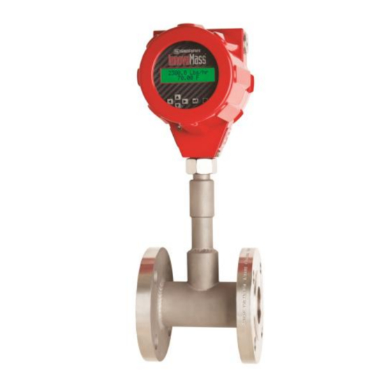
Sierra InnovaMass 241i Instruction Manual
Vortex volumetric flow& multivariable mass vortex flow meters
Hide thumbs
Also See for InnovaMass 241i:
- Preliminary instruction manual (45 pages) ,
- Instruction manual (28 pages) ,
- Instruction manual (28 pages)

Related Manuals for Sierra InnovaMass 241i


Summary of Contents for Sierra InnovaMass 241i
- Page 1 InnovaMass iSeries ® Models 240i & 241i Vortex Volumetric Flow & Multivariable Mass Vortex Flow Meters Instruction Manual Part Number: 24i-IM Version D, November 2016...
- Page 2 Sierra Instruments, Inc., is not liable for any damage or personal injury, whatsoever, resulting from the use of Sierra Instruments standard mass flow meters for oxygen gas. You are responsible for cleaning the mass flow meter to the degree required for your oxygen flow application. However, some models can only be properly cleaned during the manufacturing process.
-
Page 3: Table Of Contents
Table of Contents Chapter 1: Introduction ..........................7 Chapter 2: Installation Installation Overview ..................13 Chapter 3: Operation & Programming ....................34 Chapter 4: Troubleshooting & Repair ...................... 82 Appendix A: Product Specifications ....................... 85 Appendix B: Flow Meter Calculations ..................... 97 Appendix: C Glossary .......................... - Page 4 Warnings and Cautions Note and Safety Information We use caution and warning statements throughout this book to draw your attention to important information. General Safety Information We use caution and warning statements throughout this book to draw your attention to important information. Symbol Key Symbol Symbol...
- Page 5 If the problem persists after following the troubleshooting procedures outlined in Chapter 4 of this manual, contact Sierra Instruments by fax or by e-mail (see inside front cover). For urgent phone support you may call (800) 866-0200 or (831) 373-0200 between 8:00 a.m.
- Page 6 Register Your Product Today Warranty Statement All Sierra products are warranted to be free from defects in material and workmanship and will be repaired or replaced at no charge to Buyer, provided return or rejection of product is made within a reasonable period but no longer than one (1) year for calibration and non-calibration defects, from date of delivery.
-
Page 7: Chapter 1: Introduction
Chapter 1: Introduction InnovaMass. Reinvented. In the 1990s, Sierra designed and introduced InnovaMass, the first multivariable mass vortex flow meter in the world. Through a single process connection, InnovaMass now empowered customers with mass flow rate, volumetric flow rate, density, temperature and pressure. - Page 8 Multiple languages HART, Modbus, Profibus DP, Foundation Fieldbus, USB, RS-232 AGA-8 density equations Approvals: CE, cFMus, ATEX, PED, IECEx Raptor II OS Flow Engine Powers Advanced Field Flexibility Originally developed as the operating system for our QuadraTherm thermal mass flow meter, Raptor II OS is the “flow-engine”...
- Page 9 Very similar to the way a tree branch in a fast-flowing stream creates swirls or vortices in the downstream flow, Figure A shows the alternating vortices (1) shed by the bluff body (2) inside every InnovaMass. These vortices flex the instrument piezoelectric sensor tab (3), producing a frequency output that is directly proportional to the flow rate.
- Page 10 laminar and transitional flow in real-time as they would occur inside the pipe or duct (See Figure C). This results in increased accuracy, particularly at low flow rates of Reynolds Number of 5000 and below. Figure C. Ratio of Laminar, Transitional and Turbulent flow regimes and Reynolds number (Source: Richard Miller, Flow Measurement Engineering Handbook.) Flow Velocity Range To ensure trouble-free operation, vortex flow meters must be correctly sized so that the flow...
- Page 11 The linear range is defined by the Reynolds number. The Reynolds number is the ratio of the inertial forces to the viscous forces in a flowing fluid and is defined as: V D Re = Where Re = Reynolds Number ...
- Page 12 Both the inline and insertion configurations are similar in that they both use identical electronics and have similar sensor heads. Besides installation differences, the main difference between an inline flow meter and an insertion flow meter is their method of measurement. For an inline vortex flow meter, the shedder bar is located across the entire diameter of the flow body.
-
Page 13: Chapter 2: Installation Installation Overview
Chapter 2: Installation Installation Overview Sierra’s InnovaMass Vortex Flow Meter installations are simple and straightforward. Both the 240i Inline and 241i Insertion type flow meter installations are covered in this chapter. After reviewing the installation requirements given below, see page 14 for 240i installation instructions. - Page 14 Minimum Required Minimum Required Upstream Downstream Diameters Diameters Example 10 D 15 D 25 D 10 D 10 D 20 D 25 D 10 D D=Internal diameter of channel. N/A=Not applicable Figure 1: Recommended Pipe Length Requirements for Installation, 240i/241i Series 240i Inline Flow Meter Installation Unless otherwise noted on the application datasheet (ADS), the meter inside diameter is equal to the same size nominal pipe ID in schedule 80.
- Page 15 Note: Do not allow Shedder bar (bluff any gasket body) is positioned material to extend upstream of the into the flow profile sensor Figure 2. Flange-Style Flow Meter Installation Flange-Style Flow Meter Installation Install the flange-style meter between two conventional pipe flanges of the same nominal size as the flow meter.
- Page 16 2. Seat the meter level and square on the mating connections with the flow arrow on the upstream side, with the arrow head pointing in the direction of flow. Position a gasket in place for each side. Make sure both gaskets are smooth and even with no gasket material extending into the flow profile.
- Page 17 the gate portion of the valve. This ensures that the flow meter’s sensor head will not interfere with the operation of the isolation valve. When using toxic or corrosive gases, purge the line with inert gas for a minimum of four hours at full gas flow before installing the flow meter Cold Tap Guidelines Refer to a standard code for all pipe tapping operations.
- Page 18 Hot Tap Guidelines Hot tapping must be performed by a trained professional. U.S. regulations often require a hot tap permit. The manufacturer of the hot tap equipment and/or the contractor performing the hot tap is responsible for providing proof of such a permit. All flow meter connections, isolation valves, and fittings for hot tapping must have the same or higher pressure and temperature rating as the main pipeline.
- Page 19 Connect isolation valve and test for leaks xxxxxxxxxxxxxxxxxxxx xxxxxxxxxxxxxxxxxxxx Purge pipe xxxxxxxxxxxxxxxxxxxx xxxxxxxxxxxxxxxxxxxx Figure 4. Hot Tap Sequence Flow Meter Insertion The sensor head must be properly positioned in the pipe. For this reason, it is important that insertion length calculations are carefully followed. A sensor probe inserted at the wrong depth in the pipe will result in inaccurate readings.
- Page 20 Installing Flow Meters with a Compression Connection Use the following formula to determine insertion length for flow meters (NPT and flanged) with a compression process connection. The installation procedure is given on the next page. Figure 5. Insertion Calculation (Compression Type) Example: To install a 241i meter with a standard probe (S = 32.0 inches) into a 14-inch schedule 40 pipe, the following measurements are taken:...
- Page 21 Insertion Procedure for Meters with a Compression Connection Figure 6. Insertion Flow Meter with Compression Type Fitting The sensor alignment pointer must point downstream, in the direction of flow. To avoid serious injury, DO NOT loosen the compression fitting under pressure.
- Page 22 5. Align the sensor head using the sensor alignment pointer. Adjust the alignment pointer parallel to the pipe and pointing downstream. 6. Tighten the compression fitting to lock the stem in position. When the compression fitting is tightened, the position is permanent. Installation of Meters with Packing Gland Connection Use the following formula to determine insertion depth for meters with a packing gland connection (NPT and flanged)
- Page 23 Warranty Policy. Water penetration can lead to a damaged flow meter. Sierra’s "E" HALE ex-proof enclosures are rated to a NEMA4X, IP66 rating. This provides protection against, rain, sleet, snow and splashing water, but water can damage the sensor, electronics or wiring terminals if the meter is...
- Page 24 To minimize the potential for water damage, Sierra Instruments recommends the following: Install conduit seals near the enclosures on all ports. Use a cable gland design that provides shielded cable termination and an environmental seal against dirt and water.
- Page 25 Field wiring should be rated 80°C (176°F) or above. Flameproof/explosion proof joints should not be repaired, contact Sierra Instruments in the event that repair of the joints is necessary. General Terminal Board Layout Use the terminal blocks located inside the cap of the flow meter enclosure for all wiring connections.
- Page 26 Figure 9. Wiring Access To avoid potential electric shock, follow National Electric Code safety practices or your local code when wiring this unit to a power source and to peripheral devices. Failure to do so could result in injury or death. All AC power connections must be in accordance with published CE directives.
- Page 27 (if E4 option ordered) enclosures should be connected to earth ground, see below for more details. 1. Earthing: The Sierra Instruments units must be connected to a good quality earth. The units are provided with internal and external earthing terminals.
- Page 28 Input Power Wiring AC Power Wiring The AC power wire size must be 26 to 16 AWG with the wire stripped 1/4 inch (6 mm). Connect 100 to 240 VAC (0.2 Amps RMS at 230 VAC) to the neutral and line terminals on the terminal block.
- Page 29 DC Power Wiring The DC power wire size must be 26 to 16 AWG with the wire stripped 1/4 inch (6 mm). Connect 24 VDC +/- 10% (0.4 amp load, maximum) to the terminals marked on the terminal block. Connect the earth ground wire to the safety ground log. Torque all connections to 4.43 to 5.31 in- lbs (0.5 to 0.6 Nm).
- Page 30 4-20 mA Output Wiring All InnovaMass 240i/241i Series flow meters are equipped with calibrated 4-20 mA output signals for flow, temperature, and pressure. The 4-20 mA current loop output is non-isolated. Max load 500 ohms. Figure 13. 4-20mA Output Connections Figure 14.
- Page 31 Figure 15. AC or DC Power Supply RS-232 Wiring RS-232 provides serial communication. For RS-232, wire per Figure 16. Figure 16. RS-232 Communication...
- Page 32 Pulse Output InnovaMass provides an adjustable pulse output with a maximum of 1 Hz. Wire pulse output per Figure 17. Figure 17. Pulse Output USB Output This USB plug (J1) is used to connect to the SIP Software, per Figure 18. Figure 18.
- Page 33 When connecting more than one meter, do not intermix the sensor probes and electronics. The electronics, sensor probes and interconnecting cables supplied by Sierra Instruments are calibrated as a complete precision mass flow circuit. To make wiring connections from a sensor probe junction box to a remotely mounted enclosure, see Figure 19.
-
Page 34: Chapter 3: Operation & Programming
Chapter 3: Local Display/Interface Operation & Programming General Navigation In general terms, the menu system consists of a main menu, the set-up menu, a sub-menu to program each item in the set-up menu, and a series of data entry or pull-down screens to enter set-up data for each parameter. - Page 35 Summary of Menus/Tables 1. Main Menu: Displays Measured Variables and Initial Setup (page 34) 2. Sub Menus: Set-up, Calibration, and Diagnostics menus (page 36) 3. Calibration: Set-up Dial-A-Fluid and Dial-A-Pipe (page 36) 4. Diagnostics: Meter status and Troubleshooting (page 45) 5.
- Page 36 Tag Number 1234XXXX All of these values are also displayed on the provided SIP (Smart Interface Portal) software. Level 1: Main Menu Once set-up data is displayed, the meter will display the flow variables. The instrument will Auto Scroll through the Flow/Temp, Pressure, Density, And Totalizer (if turned on), Active Alarms (if any), and the remaining variables of Table 1, then return to repeat screens.
- Page 37 Pressure Pressure 0.00/psia Density Density lb/ft 62.4 Totalizer You can always scroll to the totalizer screen manually, but it will only auto scroll if turned on. See note above. Total Units SCF 0.00 Alarm Active Alarm Flow – L (On) Full Scale Flow Full Scale Flow 100.00 SCFM...
- Page 38 Serial Serial 1234XXXX 1234XXXX And finally complete the cycle back to the flow and temperature screen. Level 2: Sub-Menu (Password Protected) At this point, you can access various other menus. To enter the next level, press the enter key. You will be requested to enter a password. Default is 0000 and can be reset in a later screen or using SIP: Password 0000...
- Page 39 Table 3: Calibration Sub-Menu These screens, Dial-A-Pipe ID, Insertion Depth, Dial-A-Pipe Type are available only with the insertion version InnovaMass 241i. Calibration (Sub-Menu): Gas Type – Dial-A Fluid Use the “Dial-A-Fluid” sub-menu to change and select the fluid to be measured. Our Dial-A- Fluid feature is a powerful and unique feature of the 240i/241i.
- Page 40 This instrument can be moved to different pipe sizes and types as needed and perform precision flow measurement. This capability is called Dial-A-Pipe and is a powerful and unique feature of the InnovaMass 241i immersible thermal mass flow meter. The internal pipe diameter (ID), insertion depth, and pipe type are very important factors when considering flow profile.
- Page 41 Dial-A-Pipe Step 2: Navigate to the “Insertion Depth” screen. Use Table 3: Calibration Sub- Menu for guidance. Pipe insertion depth is automatically set to the pipe centerline unless adjusted here. For some large pipes where centerline placement is not possible. An insertion depth of 5 inches is suggested.
- Page 42 You can press the exit several times to climb back up to the main menu level or press to proceed to the next Calibration Sub-Menu called Flow Units. Calibration (Sub-Menu): Flow Units Navigate to the “Flow Units” screen. Use Table 3: Calibration Sub-Menu for guidance if necessary.
- Page 43 NMPS, NMPM, NMPH, NMPD, NMPY Normal Meters per Second, Minute, Day, Hour or Year. Normal conditions are set in the Reference Conditions menu. Note this is a point VELOCITY. British Thermal Units per Second, Minute, Hour, Day, or Year. Reference conditions N/A.
- Page 44 Press enter and the units will begin flashing. As in previous examples, use the buttons to enter the desired value, and the enter key to save the value. You can press the exit several times to climb back up to the main menu level or press to proceed to the next Calibration Sub-Menu called K factor.
- Page 45 Press to proceed to the next Calibration Sub-Menu called % Full Scale Cut-Off. . Calibration (Sub-Menu): % Full Scale Cut-off The InnovaMass 240i and 241i are extremely sensitive flow instruments that can pick up low flows due to leak-by or vibration and lead to totalization errors. The % Full Scale Cut-off value forces both the digital display and the analog output values to zero/4 mA at a percentage of full scale from 0 to 50% of the full scale value.
- Page 46 Calibration Date 08/13/2012 Sierra recommends recalibration as required by your metrology policy or when the meter validation routine found in the Smart Interface Portal software detects a problem. You can press the exit several times to climb back up to the main menu level or press to proceed back to the first Calibration Sub-Menu: Dial-A-Fluid.
- Page 47 Copy of Table 2: Diagnostics Sub-Menu Diagnostics (Sub-Menu) In the Diagnostics Sub-Menu, you can: Quickly determine meter status View any detected hardware errors Read the maximum and minimum values that the flow meter has measured. Tune the meter for optimal performance ...
- Page 48 Table 5: Meter Status Sub-Menu Navigate to the Diagnostics (Sub Menu). Push enter key to reach the Meter Status sub-menu. The meter will report the status of your meter as either “No Issues” or it will display the detected Error descriptions.
- Page 49 Possible Cause of Error Code 1. Temperature channel calibration is incorrect/ corrupted. Solution: Contact Sierra for remote troubleshooting. If this is not immediately possible, temperature may be simulated in the Fluid Properties sub-menu. 2. Temperature sensor has failed (often evidenced by a very HIGH temperature reading on the display).
- Page 50 Remove meter from process until Temperature is within sensor range. 2. Temperature calibration is incorrect/ corrupted. Solution: Contact Sierra for remote troubleshooting. If this is not immediately possible, temperature may be simulated in the Fluid Properties sub-menu. 3. Temperature sensor has failed (often evidenced by a very HIGH temperature reading on the display).
- Page 51 Possible Cause of Error Code 1. The pressure calibration is incorrect/ corrupted. Solution: Contact Sierra for remote troubleshooting. If this is not immediately possible, pressure may be simulated in the Fluid Properties sub-menu. 2. The sensor has failed.
- Page 52 Possible Cause of Error Code 1. The SD Card is missing. Solution: Replace the SD Card if available. Contact Sierra for a replacement SD Card. 2. The SD Card is damaged. Solution: Contact Sierra for replacement card UART Issues 240i/241i meters have multiple Universal Asynchronous Receiver/Transmitters (UART) for communications (ex.
- Page 53 1. MCU is malfunctioning. Solution: Contact Sierra for remote troubleshooting. The meter may need to be returned to the factory. 2. MCU has failed. Solution: The meter may need to be returned to the factory. Main Board Button Stuck 240i/241i meters have display buttons for navigation and data entry.
- Page 54 Go to Diagnostics, then Sensor Tune menu (See Table 6) and check Ck and Minimum Noise Level. Reset these values if necessary. Contact Sierra for remote troubleshooting. 2. Meter Earth Ground is faulty. Solution: Verify meter is properly earth grounded.
- Page 55 Navigate to the Diagnostics (Sub-menu). Push enter key to reach the next lower level. Use the left and right buttons to reach Sensor Tune sub-menu. Push the enter key to enter Sensor Tune sub-menu. Use the left and right buttons to move between menu screens under the Sensor Tune sub-menu.
- Page 56 In the example above, all frequencies above 125.35 Hz will be filtered out. Amplitude: The Amplitude menu displays the current sensor amplitude. Strong flow signals will have amplitudes in the range of 2000 to 4000. The strength of the flow signal is dependent on the density and velocity of the fluid.
- Page 57 21.1 In general, the Ck should result in a Dynamic Frequency Filter that is 20-25% higher than the actual Sensor Frequency. Frequency Hz Freq. Filter fi 10.0 12.5 As the Ck value increases, the window for detecting frequency widens and can eventually allow in anomalous higher frequencies.
- Page 58 K-Factor is a calibration constant and cannot be adjusted. Simulation Status: For the Flow and Frequency menus, use the key to navigate to the Simulation Status menu. Push the enter key to change the status. Simulate Flow Simulate Value: For the Flow and Frequency menus, use the key to navigate to the Simulation ...
- Page 59 Troubleshooting Meter Settings Use the “Sensor Tune” sub-menu to troubleshoot your meter. Watch Video Tutorial – a video tutorial for this function called “Meter Tuning” is available on the USB flash drive provided in the product shipment. Copy of Table 6: Sensor Tune Sub-Menu Case I: Meter shows no flow when you know there is flow Solution 1: Check the flow velocity.
- Page 60 Solution 1: Check the Minimum Noise Level The Minimum Noise Level may be set too low. This will allow false flow signals caused by noise or vibration to be seen. The Minimum Noise Level must be set above the level of this noise/vibration to cut it out.
- Page 61 Fluid Properties (Sub-Menu) The Fluid Properties sub-menu allows you to simulate temperature and pressure to simulate viscosity and density for fluids that are not in the meter’s fluid database. Note density and viscosity are dependent on temperature and pressure, so these values are only valid at the temperature and pressure they are specified for.
- Page 62 Viscosity Pa-s 0.0001 Reynolds Number: The Reynolds number is a dimensionless calculated value and is used for troubleshooting. In most cases, it will be above 5,000. Reynolds 25000 Simulation Status: For the Temperature, Pressure, Density, and Viscosity menus, use the ...
- Page 63 Navigate to the Diagnostics (Sub Menu). Push the enter key to reach the next lower level. Use the left and right buttons to reach the Low/High sub-menu. Hit the enter key to reach the next lower level of menu. Use the left and right buttons to move between menu screens under the Low/High sub-menu.
- Page 64 For VT or VTP meters, the minimum and maximum temperature limits are -40F to +392F (-40C to +200C). Operating outside of these limits could damage the velocity sensor. Max Pres: The Max Pres menu displays the maximum recorded pressure value along with the units.
- Page 65 The InnovaMass 240i and 241i is a can be ordered as a multivariable mass flow meter. It will always measures mass velocity (from which the mass flow rate is derived) and optionally temperature (VT option) and process pressure in addition to VT, called (VTP option). The Process Temperature and Pressure Sub-Menu allows you to input the desired units and enter the process temperature and pressure for volumetric flow only (V option) and volumetric and temperature meters (VT option).
- Page 66 The process temperature can also be simulated in the “Diagnostics Sub- menu.” For example: Process Temp 100 F This process temperature is used by the instruments’ Raptor II operating system to improve fluid property calculations. The units of the temperature in this menu are the same as what was set in the previous menu. In the example above, the units are F since this is what was set in the temperature units sub-menu.
- Page 67 Process Pressure Sub-Menu: Process Pressure Use this menu to enter the process pressure. The “Process Pressure Sub-Menu: Process Pressure” is only applicable in V and VT units, VTP will have this real time. Process Pressure 14.700000 As in previous examples, use the buttons to enter the desired value, and the enter key to save the value.
- Page 68 Totalizers are used to monitor accumulated flow, often for billing and cost allocation purposes. The totalizer sub-menu is used to turn the totalizer ON or OFF, to reset, and to tell the meter when to send out a totalizer pulse and what that pulse should look like. Table 10: Totalizer Sub-Menu Totalizer (Sub-Menu): Reset Totalizer Use this menu to reset the totalizer to zero.
- Page 69 To reset this to zero, press enter and a “Yes” will appear and flash. Reset Pulse Cnt. Use the up and down keys to toggle between “Yes” and “No”. Make your selection and then press enter to finalize the selection. If you answered YES, the count will read zero “0”.
- Page 70 several times to climb back up to the main menu level or press You can press the exit proceed to the next Sub-Menu called Units Per Pulse. Totalizer (Sub-Menu): Units Per Pulse Use this menu to select the units per pulse. Navigate to the “Units Per Pulse” screen. Use Table 5 for guidance if necessary.
- Page 71 Totalizer set up is now complete. This concludes our review of the Totalizer (Sub-Menu). Press exit to climb back up to the main menu. Alarm (Sub-Menu) The alarm sub menu controls all aspects of the 240i and 241i alarm feature. The instrument can be set to alarm on one of the following variables: flow, pressure, temperature or totalizer.
- Page 72 Only one alarm can be active at any one time. The alarm relay is a normally open isolated contact. The alarm is tripped when the relay closes. Watch Video Tutorial – a video tutorial for this function called “Local Display Interface Navigation” is available on the USB flash drive provided in the product shipment.
- Page 73 Table 12. Flow Alarms (Sub Menu) For example, we will set a low flow alarm to demonstrate the alarms function. Navigate to the Flow Alarms (Sub Menu) screen. Assume that you already set the Active Alarm to “Flow” and the alarm condition is set to go off on a “Low” flow. The Flow Alarms menu allows you to set the actual alarm setpoint along with hysteresis.
- Page 74 In the example screen above, 14.69 has been entered. The units were already set in the units menu. If you wanted to set a “High Alarm,” press the right or left key and the “High Alarm” setup screen will appear. To change the settings on either high or low, press enter ...
- Page 75 In the example screen above, 500.00 has been entered. The units were already set in the units menu. If you wanted to set a “High Alarm,” press the right or left key and the “High Alarm” setup screen will appear. To change the settings on either high or low, press enter ...
- Page 76 Full Scale Flow 100.00 SCFM Note that accuracy is still based on the original factory calibration full scale value. 4mA for flow is always set to zero flow. Factory calibration full scale is calculated for the application using the meter sizing tool.
- Page 77 Navigate to the “Flow 20mA” screen in the Output (Sub Menu). Use Table 13 for guidance. This value is the DAC value that produces 20 mA on the analog flow output. In the example screen DAC is 56643. Press enter and the units will begin flashing. Increasing this value will raise the 20mA output and decreasing this value will lower the 20mA output.
- Page 78 Pressure 4mA 0.00 Press enter key and use the use the buttons to enter the desired numeric value, and then press the enter key to save the value. Press the right key to continue to the pressure value that corresponds to the 20mA output. Pressure 20mA 30.00 In the example screen above, if your pressure units are psia then 30.00 psia would correspond to...
- Page 79 Press enter key and use the use the buttons to enter the desired numeric value, and then press the enter key to save the value. If you change these temperature low/high values the temperature accuracy is still based on the original +/-1°C specification.
- Page 80 From here you can adjust instrument reference conditions . To adjust, press again and the units will begin flashing. As in previous examples, use the buttons to enter the desired value, and press enter to save the value. Standard Temp.
- Page 81 Restore Factory (Sub-Menu): Use Restore Factory (Sub-Menu) to restore all parameters to the original factory conditions. Important: This will undo any changes you have made. Navigate to the Restore Factory (Sub-Menu). Use Table 2 for guidance. Press enter and the YES will begin flashing. As in previous examples, use the buttons to enter YES or NO, and press the enter key ...
-
Page 82: Chapter 4: Troubleshooting & Repair
Chapter 4: Troubleshooting & Repair Troubleshooting the Flow Meter Begin hardware troubleshooting by verifying the following facilities issues are correct (See below check list). These areas impact system operation and must be corrected prior to performing any flow meter inspections. 1. - Page 83 Factory Calibration—All Models Sierra Instruments maintains a fully-equipped calibration laboratory. All measuring and test equipment used in the calibration of Sierra transducers are traceable to NIST Standards. Sierra is ISO-9001 registered and conforms to the requirements of ANSI/NCSL-Z540 and ISO/IEC Guide...
- Page 84 Ship the unit(s) to the following address: Sierra Instruments, Inc. Attention: Factory Service Center 5 Harris Court, Building L Monterey, CA 93940 USA RE: RMA# (your number) For Global Service Centers, go to http://www.sierrainstruments.com/facilities.html...
-
Page 85: Appendix A: Product Specifications
Appendix A: Product Specifications... -
Page 97: Appendix B: Flow Meter Calculations
Appendix B: Flow Meter Calculations Inline Flow Meter Calculations Volume Flow Rate Mass Flow Rate Q Flowing Velocity Where: A = Cross sectional area of the pipe (ft^2) f = Vortex shedding frequency (pulses / sec) K = Meter factor corrected for thermal expansion (pulses / ft^3) = Mass flow rate (lbm / sec) = Volume flow rate (ft^3 / sec) - Page 98 = Mass flow rate (lbm / sec) = Flowing velocity (ft / sec) = Density (lbm / ft^3) Fluid Calculations The 240i and 241i density and viscosity calculations and values are determined from Sierra proprietary fluid properties algorithm based on temperature and pressure of the fluid.
-
Page 99: Appendix: C Glossary
Appendix: C Glossary A B C D Cross sectional area. ACFM Actual Cubic Feet Per Minute (volumetric flow rate). ASME American Society of Mechanical Engineers Bluff Body A non-streamlined body placed into a flow stream to create vortices. Bluff body also called a Shedder Bar. British Thermal Unit, an energy measurement. - Page 100 Liquid crystal display M N O P Mass flow rate Milli-amp, one thousandth of an ampere of current Viscosity, a measure of a fluid’s resistance to shear stress. Honey has high viscosity, alcohol has low viscosity. nm3/hr Normal cubic meters per hour (flow rate converted to normal conditions, as shipped 101 kPa and 0°...
- Page 101 scfm Standard cubic feet per minute (flow rate converted to standard conditions, as shipped 14.696 psia and 59° F). User definable. Shedder Bar A non-streamlined body placed into a flow stream to create vortices. Also called a Bluff Body. Strouhal Number (St) A dimensionless number equal to the frequency of vortices created by a bluff body times the width of the bluff body divided by the velocity of the flowing fluid (i.e., St = fd/V).
-
Page 102: Appendix D: Atex And Iecex Certified Ex Units
Appendix D: ATEX and IECEx Certified EX Units 1. Labeling Sierra Instruments Model 240i and 241i ATEX and IECEx Flow Transmitters that have the following label attached have been certified in compliance with: ATEX: EN 60079-0:2012, EN 60079-1:2014, EN 60079-31:2014, EN 60529:1991+A1:2000... - Page 103 WARNING: POTENTIAL ELECTROSTATIC CHARGING HAZARD—SEE INSTRUCTIONS 2. Type Approval Standards The Sierra Instruments ATEX/IECEx approved flow meters have an EC Type examination certificate issued by FM Approvals and have been approved to the following standards: ATEX: EN 60079-0:2012, EN 60079-1:2014, EN 60079-31:2014, EN 60529:1991+A1:2000 IECEx: IEC 60079-0:2011, IEC 60079-1:2014, IEC 60079-31:2013, IEC 60529:2001 3.
- Page 104 3.1. Area Classification Zone 1 Area in which an explosive gas atmosphere is likely to occur in normal operation occasionally Zone 2 Area in which an explosive gas atmosphere is not likely to occur in normal operation and if it does occur, is likely to do so only infrequently and will exist for a short period only Zone 21...
- Page 105 4.2. Mounting, Commissioning, and Operation The device has been designed to operate safely in accordance with the current technical and safety regulations of the EU. If installed incorrectly or used for applications for which it is not intended, it is possible that application related changes may arise. For this reason, the instrument must be installed, connected, operated, and maintained according to the instructions in this and the specific product operating manual.
- Page 106 NOTE: Please insure that when you mount these cable glands they are made-up wrench tight. At least 3-1/2 turns of the thread must be engaged inside of the electronics enclosure. 4.4. Special Conditions for a Safe Use/Specific Conditions of Use The ambient temperature must never overrun the following limits: -20…+60°C.
- Page 107 5. Remote Electronics Sierra Thermal flow transmitters with E4 in the model code have remote electronics. They have a cable with glands between the sensor and the electronics. These units are marked with the same label and markings as the non-remote E2 configuration, one label on each of the two enclosures, see section 1 for information.
- Page 108 Please make sure that the internals of the unit always stay dry and clean. There are no user maintainable components inside the electronic compartment. 7. Earthing The Sierra Instruments units must be connected to a good quality earth. The units are provided with internal and external earthing terminals. 7.1.
- Page 109 Factory Calibration—All Models Sierra Instruments maintains a fully-equipped calibration laboratory. All measuring and test equipment used in the calibration of Sierra transducers are traceable to NIST Standards. Sierra is ISO-9001 registered and conforms to the requirements of ANSI/NCSL-Z540 and ISO/IEC Guide...
- Page 110 Manufacturer: Sealcon (Hummel) 7374 S. Eagle Street Centennial, CO 80112-4221 Cable Glands used on Sierra E4 units: Sealcon: CD13NR-BE-N-ASMBLD PK=10 (Sierra Reference 30-0647) Brief Description: The Sealcon (Hummel) type cable gland is for use in the appropriate Hazardous Areas with braided shield cable.
- Page 114 Addendum B: Agency Approvals View all InnovaMass 240i/241i agency approval certificates on our website along with all documentation relating to the InnovaMass 240i/241i. InnovaMass 240i sierrainstruments.com/products/downloads/innovamass-240i InnovaMass 241 sierrainstruments.com/products/downloads/innovamass-241i...
-
Page 115: Appendix E: Warranty Policy
Appendix E: Warranty Policy Warranty Statement All Sierra products are warranted to be free from defects in material and workmanship and will be repaired or replaced at no charge to Buyer, provided return or rejection of product is made within a reasonable period but no longer than one (1) year for calibration and non-calibration defects, from date of delivery.
Need help?
Do you have a question about the InnovaMass 241i and is the answer not in the manual?
Questions and answers