Table of Contents
Advertisement
Quick Links
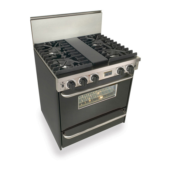
30" A
**T
HESE MODELS ARE NOT FIELD CONVERITBLE FOR
ORDERED FROM THE
**T
HESE MODELS ARE NOT FIELD CONVERTIBLE FOR
ORDERED FROM THE
I
F YOU HAVE QUESTIONS
I
NSTALLATION
P
ROFESSIONAL
G
, C
LL
AS
ONVECTION WITH
30" N
ATURAL
*TN281-7BW
*TN281-7W
F
ACTORY SET FOR
30" LP/P
ROPANE
*PN281-7BW
*PN281-7W
F
ACTORY SET FOR
,
800-251-7224, 8
CALL
,
.F
WEBSITE
WWW
I
NSTRUCTIONS
R
M
ANGE
ODELS
S
B
EALED
URNERS
G
M
AS
ODELS
LP/P
ROPANE GAS
N
LP/P
ATURAL OR
G
M
AS
ODELS
N
ATURAL GAS
N
LP/P
ATURAL OR
5
E
AM TO
PM
ASTERN
S
R
.
IVE
TAR
ANGE
COM
**
. T
HEY MUST BE
.**
ROPANE
. T
HEY MUST BE
.**
ROPANE
T
,
IME
OR VISIT OUR
.
Advertisement
Table of Contents

Subscribe to Our Youtube Channel
Related Manuals for FiveStar TTN281-7BSW


Summary of Contents for FiveStar TTN281-7BSW
- Page 1 NSTALLATION 30” A HESE MODELS ARE NOT FIELD CONVERITBLE FOR ORDERED FROM THE HESE MODELS ARE NOT FIELD CONVERTIBLE FOR ORDERED FROM THE F YOU HAVE QUESTIONS CALL WEBSITE NSTRUCTIONS ROFESSIONAL ANGE ODELS ONVECTION WITH EALED 30” N ATURAL ODELS *TN281-7BW *TN281-7W LP/P...
-
Page 2: Before You Begin
Consumer. • Note to Consumer Keep these instructions for future reference. • FiveStar recommends this product be installed by a licensed professional. • Product failure due to improper installation is not covered under the Warranty. WARNING: This appliance must be properly grounded. - Page 3 Remove, unwrap and temporarily lay aside any parts that are not attached to the range. Make sure no parts are left in the carton for accidental disposal. Carefully inspect the range for damage.
-
Page 4: Remove Packaging
REMOVE PACKAGING Before moving the range indoors: Remove outer carton and packing material from the shipping base. The range is now ready for removal from the wooden base. STEP 2 Due to the weight of these ranges, use a dolly with soft wheels to move this range. -
Page 5: Electric Connection
STEP 5 ELECTRIC CONNECTION This range must be supplied with 120 volt, 60 Hz. and connected to an individual, properly grounded branch circuit protected by a 5 amp circuit breaker or time delay fuse. The power cord of this appliance is equipped with a... -
Page 7: Installing The Backguard
LEASE READ ALL INSTRUCTIONS BEFORE STARTING INSTALLATION Remove the burner grates, griddle/grill and housing. From the front of the range, remove the Phillip screws in the rear of each burner pan (black pan where the top burners are located). From the rear of the range, remove two screws from the rear of the side panels, the upper most screw on each side. -
Page 8: Level The Range
STEP 8 LEVEL THE RANGE 1. Remove shipping tape from the leveling legs. 2. Carefully slide the range into position. Be careful not to damage the floor or entangle power cord and gas flexible tubing. 3. To adjust leveling legs, turn counter- clockwise to raise the range;... - Page 11 STEP 12 OVEN OPERATION GAS OVEN • Turn oven thermostat knob counter clockwise to 350°. • The oven burner should light within 60 seconds. STEP 13 GAS & ELECTRIC SUPPLY • Turn gas supply “on”. • Turn electric supply “on”.
- Page 12 STEP 14 CHECKLIST FOR SEALED BURNER INSTALLATION MAKE SURE ALL CONTROLS ARE IN THE “OFF” POSITION. Gas supply is “on” Electric power is “on” Check for proper seating of burner caps into burner base Burner grates in position Oven and broiler racks installed Surface burner ignition test Gas oven ignition test Check operation of convection fan...
Need help?
Do you have a question about the TTN281-7BSW and is the answer not in the manual?
Questions and answers