Table of Contents
Advertisement
Quick Links
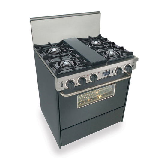
30" D
UAL
**T
HESE MODELS ARE FIELD CONVERITBLE FOR
**T
HESE MODELS ARE FIELD CONVERTIBLE FOR
I
F YOU HAVE QUESTIONS
I
NSTALLATION
P
ROFESSIONAL
F
, C
, S
UEL
ONVECTION
30" N
ATURAL
*TN275-BW
*TN275-W
30" LP/P
ROPANE
*PN275-BW
*PN275-W
,
800-251-7224, 8
CALL
,
.F
WEBSITE
WWW
I
NSTRUCTIONS
R
M
ANGE
ODELS
C
O
ELF
LEAN WITH
PEN
G
M
AS
ODELS
LP/P
G
M
AS
ODELS
N
ATURAL GAS
5
E
AM TO
PM
ASTERN
S
R
.
IVE
TAR
ANGE
COM
B
**
URNERS
.**
ROPANE GAS
.**
T
,
IME
OR VISIT OUR
.
Advertisement
Table of Contents

Related Manuals for FiveStar TTN275-W


Summary of Contents for FiveStar TTN275-W
- Page 1 NSTALLATION 30” D HESE MODELS ARE FIELD CONVERITBLE FOR HESE MODELS ARE FIELD CONVERTIBLE FOR F YOU HAVE QUESTIONS CALL WEBSITE NSTRUCTIONS ROFESSIONAL ANGE ODELS ONVECTION LEAN WITH 30” N ATURAL ODELS *TN275-BW *TN275-W 30” LP/P ROPANE ODELS *PN275-BW *PN275-W 800-251-7224, 8 AM TO ANGE...
-
Page 2: Before You Begin
Consumer. • Note to Consumer Keep these instructions for future reference. • FiveStar recommends this product be installed by a licensed professional. • Product failure due to improper installation is not covered under the Warranty. WARNING: This appliance must be properly grounded. - Page 3 Remove, unwrap and temporarily lay aside any parts that are not attached to the range. Make sure no parts are left in the carton for accidental disposal. Carefully inspect the range for damage.
-
Page 4: Remove Packaging
REMOVE PACKAGING Before moving the range indoors: Remove outer carton and packing material from the shipping base. The range is now ready for removal from the wooden base. STEP 2 Due to the weight of these ranges, use a dolly with soft wheels to move this range. - Page 5 STEP 5 CONNECTING THE RANGE TO ELECTRIC WARNING: THIS APPLIANCE MUST BE CONNECTED AS SHOWN IN FIGURE 1 OR 2. IF THE CORD IS REPLACED IT MUST BE RATED AT 250 VOLTS, 40 AMPERES AND CERTIFIED FOR USE ON HOUSEHOLD RANGES.
-
Page 7: Connecting The Range To Gas
STEP 7 (still need picture) CONNECTING THE RANGE TO GAS Because hard piping restricts movement of the range, the use of an A.G.A. certified flexible metal appliance connector is recommended unless local codes require a hard- piped connection. Never use an old connector when installing a new range. -
Page 8: Level The Range
STEP 8 LEVEL THE RANGE 1. Remove shipping tape from the leveling legs. 2. Carefully slide the range into position. Be careful not to damage the floor or entangle power cord and gas flexible tubing. 3. To adjust leveling legs, turn counter- clockwise to raise the range;... - Page 10 STEP 11 ASSEMBLE SURFACE BURNER COMPONENTS • Remove shipping screw from each surface burner. • Remove each surface burner. • Place drip pan in position under each burner. Locate “dimples”. • Re-install surface burners. • Install burner pans. • Install burner grates. STEP 12 (still need picture) SURFACE BURNER OPERATION OPEN SURFACE BURNERS...
- Page 11 STEP 15 CHECKLIST FOR OPEN BURNER INSTALLATION MAKE SURE ALL CONTROLS ARE IN THE “OFF” POSITION. Gas supply is “on” Electric power is “on” Burner drip pans in position under burners Surface burners in position Burner pans in positions Burner grates in position Oven and broiler racks installed Surface burner ignition test Gas oven ignition test...
Need help?
Do you have a question about the TTN275-W and is the answer not in the manual?
Questions and answers