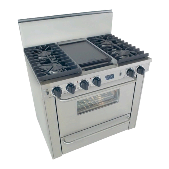
FiveStar TN331-7W Series Installation Instructions Manual
Professional range
Hide thumbs
Also See for TN331-7W Series:
- Installation instructions manual (13 pages) ,
- Installation instructions manual (12 pages)
Table of Contents
Advertisement
Quick Links
36" A
**T
HESE MODELS ARE NOT FIELD CONVERITBLE FOR
ORDERED FROM THE
**T
HESE MODELS ARE NOT FIELD CONVERTIBLE FOR
ORDERED FROM THE
I
F YOU HAVE QUESTIONS
I
NSTALLATION
P
ROFESSIONAL
G
, C
LL
AS
ONVECTION WITH
36" N
ATURAL
*TN331-7BW
*TN331-7W
F
ACTORY SET FOR
36" LP/P
ROPANE
*PN331-7BW
*PN331-7W
F
ACTORY SET FOR
,
800-251-7224, 8
CALL
,
.F
WEBSITE
WWW
I
NSTRUCTIONS
R
M
ANGE
ODELS
S
B
EALED
URNERS
G
M
AS
ODELS
LP/P
ROPANE GAS
N
LP/P
ATURAL OR
G
M
AS
ODELS
N
ATURAL GAS
N
LP/P
ATURAL OR
5
E
AM TO
PM
ASTERN
S
R
.
IVE
TAR
ANGE
COM
**
. T
HEY MUST BE
.**
ROPANE GAS
. T
HEY MUST BE
.**
ROPANE GAS
T
,
IME
OR VISIT OUR
.
Advertisement
Table of Contents

Subscribe to Our Youtube Channel
Related Manuals for FiveStar TN331-7W Series


Summary of Contents for FiveStar TN331-7W Series
- Page 1 NSTALLATION NSTRUCTIONS ROFESSIONAL ANGE ODELS 36” A ONVECTION WITH EALED URNERS 36” N ATURAL ODELS *TN331-7BW *TN331-7W LP/P HESE MODELS ARE NOT FIELD CONVERITBLE FOR ROPANE GAS HEY MUST BE LP/P ORDERED FROM THE ACTORY SET FOR ATURAL OR ROPANE GAS 36”...
- Page 2 Be sure to leave these instructions with the Consumer. Hoods should be 24" min. deep and at least the same width as the cooktop. FiveStar hoods may be installed from 24” to 30” above the Note to Consumer • Keep these instructions for future cooking surface.
- Page 3 NSTALLATION NSTRUCTIONS Please read these instructions before attempting to install this range Inspection and Unpacking Check the range carton for visible damage. If there is damage or even creases in the carton, contact the carrier, request an inspection and file the appropriate freight claim.
-
Page 4: Remove Packaging
STEP 1 REMOVE PACKAGING Before moving the range indoors: Remove outer carton and packing material from the shipping base. The range is now ready for removal from the wooden base. STEP 2 Due to the weight of these ranges, use a dolly with soft wheels to move this range. -
Page 5: Electric Connection
STEP 5 ELECTRIC CONNECTION This range must be supplied with 120 volt, 60 Hz. and connected to an individual, properly grounded branch circuit protected by a 15 amp circuit breaker or time delay fuse. The power cord of this appliance is equipped with a three-prong (grounding) plug which mates with a standard three-prong grounding wall receptacle to minimize the possibility of shock hazard from this... -
Page 7: Installing The Backguard
STEP 7 – S NSTALLING THE ACKGUARD EALED URNER ODELS LEASE READ ALL INSTRUCTIONS BEFORE STARTING INSTALLATION Remove the burner grates, griddle/grill and housing. From the front of the range, remove the Phillip screws in the rear of each burner pan (black pan where the top burners are located). -
Page 8: Level The Range
DIAGRAM FOR STEP 7 STEP 8 LEVEL THE RANGE 1. Remove shipping tape from the leveling legs. 2. Carefully slide the range into position. Be careful not to damage the floor or entangle power cord and gas flexible tubing. 3. To adjust leveling legs, turn counter- clockwise to raise the range;... -
Page 11: Griddle Operation
STEP 12 OVEN OPERATION GAS OVEN • Turn oven thermostat knob counter clockwise to 350°. • The oven burner should light within 60 seconds. GRIDDLE OPERATION • Turn griddle thermostat knob counter clockwise to 350°. • The griddle burner should light within 60 seconds. STEP 13 GAS &... - Page 12 STEP 14 CHECKLIST FOR SEALED BURNER INSTALLATION MAKE SURE ALL CONTROLS ARE IN THE “OFF” POSITION. Gas supply is “on” Electric power is “on” Check for proper seating of burner caps into burner base Burner grates in position Oven and broiler racks installed Surface burner ignition test Griddle/Grill burner ignition test Griddle/Grill assembly in position...
Need help?
Do you have a question about the TN331-7W Series and is the answer not in the manual?
Questions and answers