Table of Contents
Advertisement
Quick Links
Advertisement
Table of Contents

Summary of Contents for Deviation Devo7e
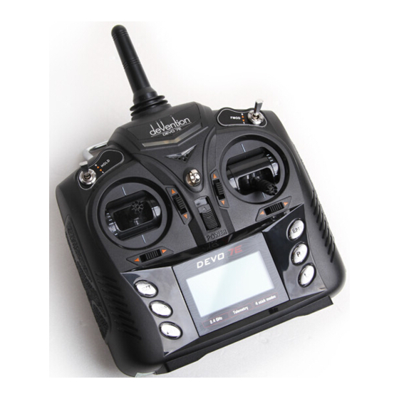
- Page 1 Deviation Firmware for Devo7e/10 User’s Manual Version 3.0...
-
Page 2: Table Of Contents
Table of Contents Overview..........................4 Installation..........................5 USB & File-system......................7 Reporting Bugs........................7 Main Page..........................8 Navigating..........................9 Menu Layout........................9 Emulator........................10 About Deviation Page......................10 USB Page...........................10 Transmitter Configuration Page..................11 General Settings......................11 Buzz Settings.........................11 LCD Settings.........................11 Timer Settings.......................11 Telemetry Settings......................11 Main Page Configuration (Standard & Advanced GUI)............12 Preview..........................12... - Page 3 Protocol: WK2401..........................23 Protocol: DSM2...........................23 Protocol: DSMX..........................23 Protocol: J6Pro............................24 Protocol: Flysky..........................24 Protocol: Hubsan4..........................24 Protocol: Frsky1 (experimental)......................25 Protocol: Frsky2 (experimental)......................25 Protocol: Skyartec (experimental).......................25 Protocol: PPM.............................25 Predefined Templates....................26 Timer Page (Standard & Advanced GUI)................27 Telemetry Configuration Page (Standard & Advanced GUI)..........28 Standard GUI........................29 Servo Reverse (Standard GUI) ..................29 Sub-trim Adjustment (Standard GUI)................29 Servo Travel Adjust (Standard GUI).................30...
-
Page 4: Overview
The core of the Deviation firmware is the mixer system, which is modeled after the system used in the Er9X firmware for the Turnigy/Flysky9x™ transmitters. -
Page 5: Installation
Installation Installation of Deviation is done just like upgrading the Walkera firmware. Note that Deviation will NOT overwrite Walkera models stored on the Tx. While they cannot be accessed by Deviation, they will be safely preserved should the Walkera firmware ever need to be reinstalled (Note: With the Devo7e firmware, the original models will be lost when switching to Deviation). - Page 6 Turn off the transmitter, and turn back on while holding ‘ENT’. There should be a USB logo on the screen. If this is a first-time install of Deviation, the PC should prompt to format the drive. Format using default options. Next unzip the deviation-fs-devoXX-x.y.z.zip to the Tx USB drive.
-
Page 7: Usb & File-System
USB & File-system Deviation stores all configuration, bitmaps, and models as regular files on the USB file- system. USB can be most easily enabled by holding down the ‘ENT’ button while powering up the transmitter. Files can then be easily copied to or from the Tx. -
Page 8: Main Page
Main Page Raw input (stick/switch values) Transmitter Power (Emulator Only) Current Model Battery voltage Model Icon Configurable Channel Output values (Emulator Only) Trims displays Current Model: The name of the current model. It is configured from the Model Configuration page. Transmitter Power: This indicates the currently selected transmitter power. -
Page 9: Navigating
For Buttons and rounded-spin-boxes, pressing ENT’ will press the button Pressing ‘EXT’ will exit 1 menu level. Menu Layout ‘ENT’ Main page Main menu Main Menu Model menu Transmitter menu About Deviation Model Menu Mixer Model Timer Main Page Config Trim Telemetry Transmitter Menu... -
Page 10: Emulator
Enter Escape Exit About Deviation Page The Deviation release version can be accessed by selecting ‘About Deviation’ from the main menu. USB Page The USB page cab be accessed by selecting ‘USB’ from the main menu. USB mode can then be toggled on/off to enable access to the transmitter’s file-system. Note that doing... -
Page 11: Transmitter Configuration Page
‘Transmitter Menu’ followed by ‘Transmitter Config’. General Settings Language: Select an appropriate language for all text (Not available on Devo7e) Stick mode: Select one of Mode 1-4. Mode 1 is common in Europe. Elevator and Rudder on left, Throttle and Aileron •... -
Page 12: Main Page Configuration (Standard & Advanced Gui)
Main Page Configuration (Standard & Advanced GUI) The Main Page Configuration page provides customized control of the main-page layout. The display of boxes, bars, icons, and trims along with their contents can all be controlled from here. This page is accessed from the main-menu via 'Model menu' followed by 'Main page config'. -
Page 13: Mixer (Advanced Gui)
'Model menu' followed by 'Mixer'. The Deviation mixer is modeled after the Er9x implementation. Each output channel is composed of a series of one or more mixers each of which consists of a single input, an activation switch, and a function/curve that modifies the mixer output. This is a very powerful capability, but it is requires a lot of understanding to make full use of. -
Page 14: Simple Template
Simple Template The simple template is the simplest manner of defining a channel. It allows defining a primary-input (stick, switch, or other channel), and applying a curve or function to that input. The result can also be scaled or have an alternate zero-offset. -
Page 15: Expo & Dual-Rate Template
Expo & Dual-Rate Template The Expo/Dual-Rate template is a more sophisticated template designed to allow use of toggle or 3-way switches to manipulate an input. The primary-input (stick, switch, or other channel), can have a different curve/function and scaling for each toggle- switch position. -
Page 16: Complex Template
Complex Template The Complex template unlocks the full power of the mixer system. For a given channel, any number of mixers can be applied to affect the final result. Each mixer is applied based on whether the specified switch is active, and can either replace, add to, or multiply to the previous mixers for this channel. - Page 17 For an ‘Add’ mux: Cx = if(Switch ) {M } else {0} + if (Switch ) {M } else {0} + … + if (Switch ) { M } else {0} For a ‘Max’ mux: Cx = MAX(if(Switch ) {M } else {0}, if (Switch ) {M } else {0}, …,...
-
Page 18: Reordering Mixers
Reordering Mixers Since the ordering of mixers is important to the output, it is possible to reorder and/or copy mixers in order to facilitate building complex rules. This page is accessed by pressing the ‘Page’ spin-box on the complex mixer page. Select the respective mixer and use the up/down buttons to move the order of the selected mixer. -
Page 19: Available Curves
Available Curves The following curve functions are supported: 1-to-1: Output is equal to the input (not editable). Fixed: Output is constant regardless of input (not editable). Min/Max: Output is -100 if input is < 0 and 100 if input is >= 0 (not editable) Zero/Max: Output is 0 if input is <... -
Page 20: Channel Configuration
Channel configuration The Channel configuration provides the ability to configure the final channel outputs. Capabilities such as channel reverse and fail- safe values are applied here. Also available are controls for end-points, scaling, sub-trim, and a safety switch (which could be used to ensure that a motor cannot spin-up while working on a model) Changes to this page will immediately effect the channel output. -
Page 21: Trims And Virtual Inputs (Standard & Advanced Gui)
Trims and Virtual Inputs (Standard & Advanced GUI) The trim page allows assigning the trim buttons and trim step, as well as configuring buttons to work as virtual inputs. It s accessed from the main menu via 'Model menu' followed by 'Trims'. If the ‘Input’... -
Page 22: Protocols
‘Re-Init’, which can be used to switch protocols without power-cycling the transmitter. Mixer GUI: Defines which GUI to use for this model. The ‘Advanced’ GUI is the default for Deviation. The ‘Standard’ GUI is only available for Helicopter models and more closely resembles a traditional vendor GUI. -
Page 23: Protocol: Wk2401
While the DSM2 protocol can support up to 14 channels, Deviation is currently limited to a maximum of 12. Note that many receivers with less than 8 channels require the Transmitter to send 7 or less channels. Make sure the # of channels is set appropriately for the receiver. -
Page 24: Protocol: J6Pro
The DSMX protocol also supports enabling/disabling the telemetry capability. This option is accessed by pressing the Protocol spin-box when DSMX is shown. Protocol: J6Pro The J6Pro protocol is used to support Nine Eagles™ models. Only models compatible with the J6Pro transmitter can be used. Many older 4-channel Nine Eagles models used a different protocol that is unsupported. -
Page 25: Protocol: Frsky1 (Experimental)
The FixedID has no effect, and there is no binding associated with this protocol. Deviation does not auto-detect when a trainer cord is plugged into the transmitter. To use Deviation with a simulator (such as Phoenix), create a new model, name it appropriately, and select PPM as the protocol. -
Page 26: Predefined Templates
A template does not completely replace your existing model, but instead only a portion of it. The currently supported templates will replace the mixer and trim definitions, but will not affect the display layout. In the future Deviation will support templates that only affect the display layout without affecting the mixers as well. -
Page 27: Timer Page (Standard & Advanced Gui)
Timer Page (Standard & Advanced GUI) The timer page defines up to 4 available timers. Timers can count either up or down, and can be enabled either manually from the main screen or by an input trigger (stick or switch). Timers can also be optionally configured to be reset via an alternate switch (only when using the Advanced GUI). -
Page 28: Telemetry Configuration Page (Standard & Advanced Gui)
Telemetry Configuration Page (Standard & Advanced GUI) The telemetry configuration page allows specifying alarms when specific telemetry events occur. This page is accessed from the main menu via 'Model menu' followed by 'Telemetry' Telemetry: Specify the telemetry input to use for alarm control. -
Page 29: Standard Gui
Standard GUI The Standard GUI is an alternative interface from the Advanced GUI’. Which interface is used is chosen by the ‘Mixer GUI’ on the Model Page. The Standard GUI is only available for Helicopter-type models at this time. The pages of the Standard GUI are as follows: 1. -
Page 30: Servo Travel Adjust (Standard Gui)
Servo Travel Adjust (Standard GUI) The servo-travel adjust page configures the maximum positive/negative travel of each servo. This is equivalent to the ‘Scale+’ and ‘Scale-’ settings on the Channel Configuration sub-page of the Mixer menu when using the Advanced Mixer (see page 20) Swash Configuration (Standard GUI) The Swash configuration page configures the swash type. -
Page 31: Pitch Curve (Standard Gui)
Pitch Curve (Standard GUI) The pitch curve allows defining a piece-wise linear curve for the collective/pitch channel. Different curves can be selected for each flight- mode as well as for throttle-hold. Each point value can be enabled to be interpolated from the points surrounding it.