Advertisement
weiderfitness.com
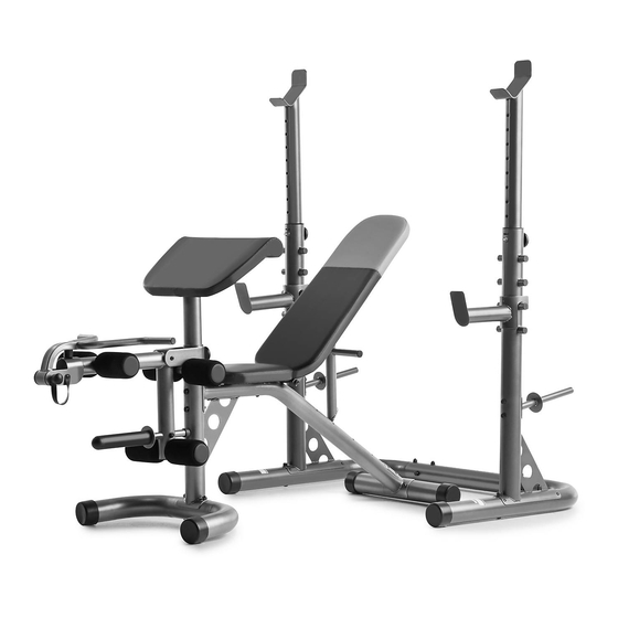
Model No. WEBE1486.0
Serial No.
Write the serial number in the space
above for reference.
Serial Number Decal (under seat)
REGISTER YOUR
PRODUCT
To register your product and
activate your warranty today,
go to my.weiderfitness.com.
CUSTOMER CARE
For service at any time, go to
support.weiderfitness.com.
Or call 1-877-992-5999
Mon.–Fri. 6 a.m.–6 p.m. MT
Sat. 8 a.m.–12 p.m. MT
Please do not contact the store.
CAUTION
Read all precautions and
instructions in this manual before
using this equipment. Keep this
manual for future reference.
USER'S MANUAL
Advertisement
Table of Contents

Related Manuals for Weider XRS 20


Summary of Contents for Weider XRS 20
- Page 1 weiderfitness.com Model No. WEBE1486.0 Serial No. USER’S MANUAL Write the serial number in the space above for reference. Serial Number Decal (under seat) REGISTER YOUR PRODUCT To register your product and activate your warranty today, go to my.weiderfitness.com. CUSTOMER CARE For service at any time, go to support.weiderfitness.com.
-
Page 2: Table Of Contents
Apply the decal in the location shown. Note: The decal(s) may not be shown at actual size. WEIDER is a registered trademark of ICON Health & Fitness, Inc. -
Page 3: Important Precautions
IMPORTANT PRECAUTIONS WARNING: To reduce the risk of serious injury, read all important precautions and instructions in this manual and all warnings on your weight bench before using your weight bench. ICON assumes no responsibility for personal injury or property damage sustained by or through the use of this product. - Page 4 STANDARD SERVICE PLANS...
-
Page 5: Before You Begin
® XRS 20 reading this manual, please see the front cover of this weight bench. The XRS 20 weight bench offers a manual. To help us assist you, note the product model selection of exercises designed to develop the major number and serial number before contacting us. -
Page 6: Part Identification Chart
PART IDENTIFICATION CHART Use the drawings below to identify small parts used in assembly. The number in parentheses by each drawing is the key number of the part, from the PART LIST near the end of this manual. IMPORTANT: If you cannot find a part in the hardware kit, check to see if it has been preassembled. -
Page 7: Assembly
ASSEMBLY 1. To use the assembly steps in this manual, first see the helpful tips below. • To hire an authorized service technician to • In addition to the included tool(s), assembly assemble this product, call 1-800-445-2480. requires the following tool(s): two adjustable wrenches •... - Page 8 3. Orient the Rear Stabilizer (3) so that the warning decals (B) are in the locations shown. Attach the Rear Stabilizer (3) to the Frame (1) with two M10 x 90mm Carriage Bolts (40) and two M10 Locknuts (57); do not tighten the Locknuts yet.
- Page 9 5. Attach the Frame (1) to the Front Leg (4) with two M10 x 85mm Bolts (43), two M10 Washers (52), and an M10 Locknut (57); do not tighten the Locknut yet. Finish attaching the Front Leg (4) to the Frame (1) with four M4 x 19mm Screws (51);...
- Page 10 7. Apply grease to an M10 x 165mm Bolt (49). Attach the Backrest Frames (16) to the Frame (1) with the Bolt, two M10 Washers (52), and an M10 Locknut (57). Then, set the end of the Grease Backrest Post (15) in one of the slots (F) in the Frame.
- Page 11 9. Insert the Long Pad Tube (36) into the bracket (G) on the Front Leg (4). Then, slide a Foam Pad (22) onto each end of the Long Pad Tube, and press a Pad Cap (23) into each end of the Long Pad Tube.
- Page 12 12. Insert an M10 x 90mm Carriage Bolt (40) upward into the Left Upright Base (9). This Bolt will be used in a later step. Attach the Left Upright Base (9) to the Base (7) with two M10 x 90mm Carriage Bolts (40), an M10 x 90mm Bolt (42), four M10 Washers (52), and three M10 Locknuts (57);...
- Page 13 14. Set a Safety Spotter (13) on a set of pegs (H) on the left Upright (11). Set the other Safety Spotter (13) on a set of pegs (H) on the right Upright (11). Make sure that both Safety Spotters are at the same height.
-
Page 14: Adjustment
ADJUSTMENT The weight bench is designed to be used with your own weight set (not included). The steps below explain how the weight bench can be adjusted. See EXERCISE GUIDELINES on page 16 for important exercise information, and refer to the accompanying exercise guide to see the correct form for several exercises. Refer also to the exercise information accompanying your weight set for additional exercises. - Page 15 USING THE LEG LEVER To use the Leg Lever (5), slide a weight plate (C) (not included) onto the Olympic Adapter (8) and secure it with a Weight Clip (41). Note: When using the Leg Lever, remove the Curl Bar (17) (see REMOVING THE CURL BAR below).
-
Page 16: Exercise Guidelines
EXERCISE GUIDELINES FOUR TYPES OF STRENGTH WORKOUTS to determine the appropriate length of time for each workout, and the numbers of repetitions and sets to Note: A “repetition” is one complete cycle of an complete. Progress at your own pace and be sensitive exercise, such as one sit-up. -
Page 17: Part List
PART LIST Model No. WEBE1486.0 R1220A Key No. Qty. Description Key No. Qty. Description Frame Tether Front Stabilizer Adjustment Knob Rear Stabilizer Long Pad Tube Front Leg Upright Bushing Leg Lever Upright Spacer Curl Post Foot Base M10 x 90mm Carriage Bolt Olympic Adapter Weight Clip Left Upright Base... -
Page 18: Exploded Drawing
EXPLODED DRAWING A Model No. WEBE1486.0 R1220A... - Page 19 EXPLODED DRAWING B Model No. WEBE1486.0 R1220A...
-
Page 20: Ordering Replacement Parts
ORDERING REPLACEMENT PARTS To order replacement parts, please see the front cover of this manual. To help us assist you, be prepared to provide the following information when contacting us: • the model number and serial number of the product (see the front cover of this manual) •...
Need help?
Do you have a question about the XRS 20 and is the answer not in the manual?
Questions and answers