Table of Contents
Advertisement
Quick Links
Smart encoders & actuators
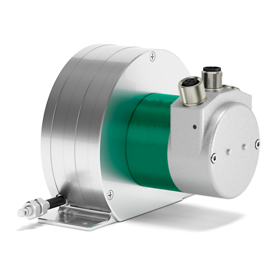
SFA-5000-CB
SFA-10000-CB
• 5000 mm & 10000 mm draw-wire encoder
• Integrated 25 bit multiturn absolute encoder
• Programmable resolution down to 24 µm
• Cable and M12 connectors options
• CANopen complying with DS 301 and DS 406 profiles
Suitable for the following models:
SFA-5000-CB
•
SFA-10000-CB
•
Lika Electronic
User's guide
•
Tel. +39 0445 806600
in compliance with DS301 & DS406 profiles
Table of Contents
•
info@lika.biz
19
21
22
26
35
37
79
83
•
www.lika.biz
Advertisement
Table of Contents

Subscribe to Our Youtube Channel
Related Manuals for Lika CANopen SFA-5000-CB


Summary of Contents for Lika CANopen SFA-5000-CB
-
Page 1: Table Of Contents
2 - Identification SFA-10000-CB • 3 - Mounting instructions 4 - Electrical connections 5 - Quick reference 6 - CANopen® interface 7 - Setting-up 8 - Default parameters list Lika Electronic • Tel. +39 0445 806600 • info@lika.biz • www.lika.biz... - Page 2 Tous droits réservés. This document and information contained herein are the property of Lika Electronic s.r.l. and shall not be reproduced in whole or in part without prior written approval of Lika Electronic s.r.l. Translation, reproduction and total or partial modification (photostat copies, film and microfilm included and any other means) are forbidden without written authorisation of Lika Electronic s.r.l.
-
Page 3: General Contents
General contents User's guide......................................1 General contents.....................................3 Subject index.....................................6 Typographic and iconographic conventions........................7 Preliminary information................................8 Glossary of CANopen terms..............................9 1 - Safety summary..................................19 1.1 Safety......................................19 1.2 Electrical safety..................................19 1.3 Mechanical safety................................20 2 - Identification..................................21 3 - Mounting instructions..............................22 3.1 Overall dimensions................................22 3.2 Mounting instructions..............................23 3.3 Useful information................................24 3.4 Maintenance..................................25... - Page 4 1000-00 Device type..............................45 1001-00 Error register..............................45 1003 Predefined error field............................45 1005-00 COB-ID SYNC message...........................45 1008-00 Manufacturer device name.........................45 1009-00 Manufacturer hardware version......................45 100A-00 Manufacturer software version.......................45 100C-00 Guard time..............................46 100D-00 Life time factor............................46 1010-01 Store parameters............................46 1011-01 Restore default parameters........................46 1014-00 COB-ID EMCY..............................47 1015-00 Inhibit time...
- Page 5 6506-00 Supported warnings..........................72 6507-00 Profile and software version......................72 6508-00 Operating time............................73 6509-00 Offset value..............................73 650A-01 Manufacturer offset value........................73 650B-00 Serial number..............................73 6.9 SDO abort codes..................................74 6.10 Emergency (EMCY) messages............................75 6.11 Node guarding protocol..............................76 7 - Setting-up....................................79 7.1 Setting the Operational, Pre-operational state......................79 7.2 Setting the resolution per revolution.........................79 7.3 Setting the total resolution............................79 7.4 Setting the Operating parameters..........................79...
-
Page 6: Subject Index
Subject index 6506-00 Supported warnings........72 6507-00 Profile and software version....72 1000-00 Device type............45 6508-00 Operating time..........73 1001-00 Error register...........45 6509-00 Offset value.............73 1003 Predefined error field.........45 650A-01 Manufacturer offset value.......73 1005-00 COB-ID SYNC message.......45 650B-00 Serial number..........73 1008-00 Manufacturer device name......45 1009-00 Manufacturer hardware version....45 100A-00 Manufacturer software version.....45 COB-ID of TPDO1.............48... -
Page 7: Typographic And Iconographic Conventions
Typographic and iconographic conventions In this guide, to make it easier to understand and read the text the following typographic and iconographic conventions are used: parameters and objects both of the device and the interface are coloured in GREEN; • alarms are coloured in RED;... -
Page 8: Preliminary Information
Preliminary information This guide is designed to provide the most complete and exhaustive information the operator needs to correctly and safely install and operate the SFA-5000 and SFA-10000 absolute draw-wire encoders with CANopen interface. The cable pulling mechanism integrates a 13 x 12 bit absolute multiturn encoder (13 bits = singleturn resolution = 8,192 cpr;... -
Page 9: Glossary Of Canopen Terms
Glossary of CANopen terms CANopen, like many other networking systems, has a set of unique terminology. Table below contains a few of the technical terms used in this guide to describe the CANopen interface. They are listed in alphabetical order. The Glossary is owned and copyrighted by the CAN in Automation international users' and manufacturers' group. - Page 10 device recovers from bus off state, it has to transmit the boot- up message and it is recommended to send an Emergency message with the appropriate error code. Controller Area Network (CAN) is a serial bus system originally developed by the Robert Bosch GmbH. It is internationally standardized by ISO 11898-1.
- Page 11 loop controllers supports also multi-channel devices. CiA DS 406 The CANopen device profile for encoders defines the communication of rotating as well as linear sensors. The draft standard proposal for programmable CANopen CiA DSP 302 devices includes CANopen manager functions, dynamic SDO connections, standardized boot-up procedure for NMT Slaves as well as program download.
- Page 12 the interface for feeder sub-systems. CiA DSP 415 The CANopen application profile for asphalt pavers specifies interfaces to different devices used in road construction machinery. CiA DSP 416 The CANopen application profile for building doors specifies interfaces for locks, sensors, and other devices used in electronically controlled building doors.
- Page 13 Conformance test plan Definitions of test cases that have to be passed successfully in order to achieve conformance to a communication standard. The conformance test plan for CAN is standardized by ISO 16845. Conformance test tool A conformance test tool is the implementation of a conformance test plan.
- Page 14 Error control message The CANopen error control messages are mapped to a single 1-byte CAN data frame assigned with a fixed identifier that is derived from the device's Node ID. It is transmitted as boot-up Pre-operational message before entering state after initialization, and it is transmitted if remotely requested by the NMT Master (node guarding) or periodically by the device (heart-beat).
- Page 15 Index 16-bit address to access the CANopen dictionary; for array and records the address is extended by an 8-bit Subindex. Inhibit timer Object in CANopen for PDOs and Emergency messages that forbids for the specified time (inhibit time) a transmission of this communication object.
- Page 16 NMT state machine The NMT state machines support different states and the highest prior CAN message transmitted controls the transition to the states by the NMT Master. Node guarding Mechanism used in CANopen and CAL to detect bus off or disconnected devices.
- Page 17 the corresponding data frame identified by the very same identifier. The remote frame's DLC has the value of the corresponding data frame DLC. The data field of the remote frame has a length of 0 byte. Remote transmission Bit in the arbitration field indicating if the frame is a remote frame (recessive value) or a data frame (dominant value).
- Page 18 sample the inputs mapped into synchronous TPDOs. Receiving this message causes the node to set the outputs to values received in the previous synchronous RPDO. Termination resistor In CAN high-speed networks with bus topology, both ends are terminated with resistors in order to suppress reflections. TIME message Standardized message in CANopen containing the time as a 6- byte value given as ms after midnight and days after 1st...
-
Page 19: Safety Summary
failure to comply with these precautions or with specific warnings elsewhere in this manual violates safety standards of design, manufacture, and intended use of the equipment; Lika Electronic assumes no liability for the customer's failure to comply with these requirements. 1.2 Electrical safety ... -
Page 20: Mechanical Safety
SFA-5000 • SFA-10000 CANopen® 1.3 Mechanical safety Install the device following strictly the information in the “3 - Mounting instructions” section on page 22; mechanical installation has to be carried out with stationary mechanical parts; do not disassemble the unit; ... -
Page 21: Identification
Information is listed in the delivery document too. Please always quote the order code and the serial number when reaching Lika Electronic for purchasing spare parts or needing assistance. For any information on the technical characteristics of the product refer to the technical catalogue. -
Page 22: Mounting Instructions
SFA-5000 • SFA-10000 CANopen® 3 - Mounting instructions WARNING Installation, electrical connection and maintenance operations must be carried out by qualified personnel only, with power supply disconnected. Mechanical components must be in stop. 3.1 Overall dimensions Values are expressed in mm MAN SFA_5000_10000_CB E 1.0.odt 3 - Mounting instructions 22 of 88... -
Page 23: Mounting Instructions
SFA-5000 • SFA-10000 CANopen® 3.2 Mounting instructions Fasten the draw-wire unit onto a fixed support using three M4 screws 1; • remove the safety wire that pins the end of the measuring wire during • transport; fix the end of the measuring wire to the moving unit using the provided •... -
Page 24: Useful Information
SFA-5000 • SFA-10000 CANopen® Never release the wire freely, always help the wire wind properly: risk of personal injury and/or equipment damage. Always keep the wire aligned not to damage the equipment (maximum deviation: 3°). 3.3 Useful information If you want to know the maximum measuring length and the physical linear resolution of the draw-wire encoder please refer to the order code. -
Page 25: Maintenance
SFA-5000 • SFA-10000 CANopen® Number of information = 204,800 EXAMPLE 2 SFA-10000-CB-8192-M12 using a custom resolution (Scaling function in 6000-00 Operating parameters = 1) Stroke per turn of the drum = 200 mm (7.874”) 6501-00 Physical singleturn resolution, physical resolution per turn = 13 bits = 8,192 cpr 6502-00 Number of hardware distinguishable revolutions, number of... -
Page 26: Electrical Connections
SFA-5000 • SFA-10000 CANopen® 4 - Electrical connections WARNING Installation, electrical connection and maintenance operations must be carried out by qualified personnel only, with power supply disconnected. Mechanical components must be in stop. 4.1 Connection cap WARNING Do not remove or mount the connection cap with power supply switched ON. Damage may be caused to internal components. - Page 27 SFA-5000 • SFA-10000 CANopen® To remove the connection cap loosen the two screws 1. Please be careful when you disconnect the internal connector. Always replace the connection cap at the end of the operation. Take care in re- connecting the internal connector. Tighten the screws 1 using a tightening torque of approx.
-
Page 28: Connection Cap With Pg Gland (Cable Output)
SFA-5000 • SFA-10000 CANopen® 4.2 Connection cap with PG gland (cable output) Cable output versions (...-PG order code) are fitted with two PG9 cable glands for BUS IN and BUS OUT connections as well as for power supply. The bus cables can be connected directly to the terminal connectors located by each cable gland. -
Page 29: Connection Cap With M12 Connectors
SFA-5000 • SFA-10000 CANopen® 4.3 Connection cap with M12 connectors Connector output versions (...-M12 order code) are fitted with two M12 connectors with pin-out in compliance with the CANopen® standard. Therefore you can use standard CAN cordsets and patchcords commercially available. For a complete list of the available cordsets and patchcords please refer to the product datasheet (“Accessories”... -
Page 30: Ground Connection
Lika's EC- pre-assembled cables are fitted with shield connection to the connector ring nut in order to allow grounding through the body of the device. Lika's E- connectors have a plastic gland, thus grounding is not possible. If metal connectors are used, connect the cable shield properly as recommended by the manufacturer. -
Page 31: Setting The Baud Rate: Dip A
SFA-5000 • SFA-10000 CANopen® 4.6 Setting the baud rate: DIP A WARNING Power supply must be turned off before performing this operation! The transmission rate (baud rate) can be set both via hardware by using the DIP A dip switch and via 3000-00 Baud rate software (see the object). -
Page 32: Setting The Node Address: Dip B
SFA-5000 • SFA-10000 CANopen® Set the baud rate to 500Kbit/s: = 101 (binary value, see the table above) 4.7 Setting the node address: DIP B WARNING Power supply must be turned off before performing this operation! The node address can be set both via hardware by using the DIP B dip switch and 3001-00 Node-ID via software (see the... -
Page 33: Setting The Rt Bus Termination
SFA-5000 • SFA-10000 CANopen® Set the node address = 55: = 0011 0111 (binary value) OFF OFF WARNING If the baud rate and the node address are set via software, the Master device has to detect the baud rate of the Slave (scanning of baud rate) when the encoder is being installed. -
Page 34: Diagnostic Leds
SFA-5000 • SFA-10000 CANopen® 4.7 Diagnostic LEDs Two LEDs located in the connection cap are designed to show visually the operating or fault status of the CANopen® interface. RUN LED Description (GREEN) Operational The encoder is in state Stopped Single flash The encoder is in state Pre-Operational... -
Page 35: Quick Reference
SFA-5000 • SFA-10000 CANopen® 5 - Quick reference Using the default settings provided by the manufacturer, you can switch on the device and read immediately its position. Follow the instructions below to: read the physical resolution of the device: physical singleturn resolution (6501-00 Physical singleturn resolution) and number of physical Number... - Page 36 SFA-5000 • SFA-10000 CANopen® Setting the cyclic time: 6200-00 Cyclic time (100 ms = 64h) Master Encoder COB-ID Index Process data 600+ID Encoder Master COB-ID Index Process data 580+ID Setting the Operational mode Master Encoder COB-ID Node Reading the position every 100 ms Encoder ...
-
Page 37: Canopen® Interface
SFA-5000 • SFA-10000 CANopen® 6 - CANopen® interface Lika draw-wire encoders are always Slave devices and comply with the “Device profile for encoders”, Class 2. For any omitted information concerning the CANopen® protocol, refer to the “CiA Draft Standard Proposal 301. Application Layer and Communication Profile”... -
Page 38: Initialization State
SFA-5000 • SFA-10000 CANopen® Power on Initialization carried out, boot-up message is sent automatically NMT message: Start remote node NMT message: Enter pre-operational NMT message: Stop remote node NMT message: Reset node or Reset communication 6.2.1 Initialization state This is the first state the CANopen® device enters after the power is turned on or after a hardware reset (Reset node command). -
Page 39: Communication Objects
SFA-5000 • SFA-10000 CANopen® NOTE Please refer to the “7 - Setting-up” section on page 79 for an example of how the states are to be set. 6.3 Communication objects Four different kinds of communication messages are used in a CANopen® network: ... -
Page 40: Pre-Defined Connection Set
SFA-5000 • SFA-10000 CANopen® 6.3.1 Pre-defined connection set Master Slave broadcast Type of COB Function code COB-ID (hex) (Object) (binary) 0000 SYNC 0001 Peer-to-peer transmission EMERGENCY 0001 081 - 0FF PDO 1 (tx) 0011 181 - 1FF PDO 2 (tx) 0101 281 - 2FF PDO 3 (tx) -
Page 41: Boot-Up Objects
SFA-5000 • SFA-10000 CANopen® 6.5 Boot-up objects Boot-up message structure: COB-ID (hex) 1 CAN Data Byte 700+Node ID 6.6 PDO objects PDO (tx) messages are always made up of four CAN Data Bytes and are used by the encoder to transmit the position value and/or the velocity value. PDO structure: IDENTIFIER 4 CAN Data Bytes... -
Page 42: Pdo4 Cyclic Mode: Cyclic Transmission Of Velocity Value
SFA-5000 • SFA-10000 CANopen® The SYNC transmission mode can be enabled (or disabled) by setting to 0 (or 1) (1801 TPDO the most significant bit (MSB) of COB-IB used by PDO communication parameter 2 1802 TPDO communication parameter sub1 objects). PDO4 Cyclic mode: cyclic transmission of velocity value The encoder uses the PDO4 message to transmit the velocity value cyclically, i.e. -
Page 43: Command
SFA-5000 • SFA-10000 CANopen® 6.7.1 Command The command byte contains the type of telegram transmitted to the CAN network. The main types of COB telegram are as follows: Set: it is used to send the configuration parameters to a device; ... - Page 44 SFA-5000 • SFA-10000 CANopen® The Standardised Device Profile Area at indexes from 6000h to 9FFFh contains all data objects common to a class of devices that can be read or written via the network. The device profiles may use entries from 6000h to 9FFFh to describe the device parameters and the device functionality.
-
Page 45: Communication Profile Area Objects (Ds 301)
Default = 0000 0080h (CANopen device generates SYNC message) 1008-00 Manufacturer device name [String, ro] It shows the name of the device (manufacturer). Default = “LIKA srl” 1009-00 Manufacturer hardware version [String, ro] It shows the hardware version of the device. -
Page 46: 100C-00 Guard Time
[Unsig32, rw] This object allows the operator to restore all parameters to default values (default values are set at the factory by Lika Electronic engineers to allow the operator to run the device for standard operation in a safe mode). -
Page 47: 1014-00 Cob-Id Emcy
SFA-5000 • SFA-10000 CANopen® Encoder Master (confirmation) COB-ID Index Data bytes 580+ID Master Encoder (Reset node) COB-ID Slave ID Encoder Master (Boot-up) COB-ID 700+ID NOTE Save the default values after upload using the store parameters function (see 1010-01 Store parameters object). -
Page 48: 1800 Tpdo Communication Parameter 1
SFA-5000 • SFA-10000 CANopen® 1800 TPDO communication parameter 1 PDO1 message is used by default for cyclic transmission of the position value. For more information refer to the “6.6 PDO objects” section on page 41. 6200-00 Cyclic time See the object to set the cyclic timer. -
Page 49: 1801 Tpdo Communication Parameter 2
SFA-5000 • SFA-10000 CANopen® profile specific 6200-00 Default = FEh (cyclic transmission, see hereafter and the Cyclic time object) WARNING Following an attempt to set the Transmission Type to 0, the value is accepted but the PDO message is not sent; following an attempt to change the Transmission Type to any other value that is not supported by the device, an abort message (abort code = 0609 0030h: Value... - Page 50 SFA-5000 • SFA-10000 CANopen® WARNING It is mandatory to set the bit 30 of COB-ID to 1 (value 0 is not allowed). This means that “No RTR is allowed on the PDO”. If the node address is set using the internal dip-switches (i.e. at least one dip-switch for setting the node has HIGH logic level = 1), when the power is turned on, this object is always forced to the default value.
-
Page 51: 1802 Tpdo Communication Parameter 3
SFA-5000 • SFA-10000 CANopen® 1802 TPDO communication parameter 3 PDO3 message is used by default for synchronous transmission of the position value. For more information refer to the “6.6 PDO objects” section on page 41. 01 COB-ID of TPDO3 [Unsigned32, rw] Bit number Value Meaning PDO exists / is valid... -
Page 52: 1803 Tpdo Communication Parameter 4
SFA-5000 • SFA-10000 CANopen® Default = 01h (synchronous transmission at each SYNC command) The position value is transmitted after the set number of SYNC commands. The interval between the SYNC commands must be set next to this 1802 TPDO communication parameter 3, sub 2 object. - Page 53 SFA-5000 • SFA-10000 CANopen® WARNING It is mandatory to set the bit 30 of COB-ID to 1 (value 0 is not allowed). This means that “No RTR is allowed on the PDO”. If the node address is set using the internal dip-switches (i.e. at least one dip-switch for setting the node has HIGH logic level = 1), when the power is turned on, this object is always forced to the default value.
-
Page 54: 1A00-01 Tpdo Mapping Parameter 1
SFA-5000 • SFA-10000 CANopen® NOTE - The transmission of PDO1, PDO2, PDO3 and PDO4 messages can be enabled (or disabled) by setting to “0” (or “1”) the most significant bit (msb) used by the PDO (180xh, sub1 object). - The cyclic transmission or synchronous transmission can be modified by setting the 180xh sub 2 object. -
Page 55: 1A03-01 Tpdo Mapping Parameter 4
SFA-5000 • SFA-10000 CANopen® 1A03-01 TPDO mapping parameter 4 [Unsig32, rw] This object contains the mapping of the PDO the encoder uses to transmit the velocity value , according to the manufacturer profile. This object describes the content of the PDO by its index, sub-index and length. The length contains the length of the application object expressed in bits. -
Page 56: Manufacturer Specific Profile Area Objects
SFA-5000 • SFA-10000 CANopen® 6.8.2 Manufacturer Specific Profile Area objects 2104-00 Limit switch min. [Unsigned32, rw] This object is used to set the lowest software limit switch (-). If the encoder position is greater than the value set in this object, then the bit 6500-00 Operating status 12 of the object will be set to “0”. -
Page 57: 3001-00 Node-Id
SFA-5000 • SFA-10000 CANopen® To change the baud rate value you have to: 3000-00 Baud rate set the object; send a Reset node command (or Reset communication command); save the parameter; set the Master to the new baud rate. Default = 05h Master ... -
Page 58: 3005-00 Velocity Format
SFA-5000 • SFA-10000 CANopen® Default = 01h Master Encoder COB-ID Index Data byte 600+ID new Node-ID Encoder Master (confirmation) COB-ID Index Data byte 580+ID Master Encoder (Reset node) COB-ID Slave ID old ID Encoder Master (Boot-up with new Node-ID) COB-ID 700+ID NOTE... -
Page 59: Standardised Device Profile Area Objects (Ds 406)
SFA-5000 • SFA-10000 CANopen® 6.8.3 Standardised Device Profile Area objects (DS 406) 6000-00 Operating parameters [Unsigned16, rw] Function bit = 0 bit = 1 Count up Count up information information Code sequence rewinding the pulling the wire wire out not used Scaling function disabled enabled... -
Page 60: Limit Switch Min
SFA-5000 • SFA-10000 CANopen® 6002-00 Total measuring range object. The total custom resolution in the object must be equal to or less than the maximum physical value (6501-00 Physical singleturn resolution 6502-00 Number of hardware distinguishable revolutions). Default = 0 To know whether the Scaling function is currently enabled, you can read the bit 2 Scaling function of the 6500-00 Operating status... - Page 61 SFA-5000 • SFA-10000 CANopen® This object sets a custom number of distinguishable steps per revolution (custom singleturn resolution). To avoid counting errors, check that 6501-00 Physical singleturn resolution = integer value. 6001-00 Measuring units per revolution You are allowed to set whatever integer value less than or equal to the maximum number of physical steps per revolution (see the hardware counts 6501-00 Physical per revolution in the encoder identification label and the...
-
Page 62: 6002-00 Total Measuring Range
SFA-5000 • SFA-10000 CANopen® (6002-00 Total 33,554,432 measuring range) Number of revolutions = = 93,206.755... (6001-00 Measuring units per revolution) As you can see, the encoder is required to carry out more than 93,000 revolutions, this cannot be as the hardware number of revolutions is, as stated, 6502-00 Number of hardware distinguishable revolutions 4,096 (see the object). - Page 63 SFA-5000 • SFA-10000 CANopen® Setting the total resolution 6002-00 Total measuring range =0200 0000h) Master Encoder (Set request) COB-ID Index Process data 600+ID Encoder Master (Set confirmation) COB-ID Index Process data 580+ID WARNING 6002-00 Total measuring range When you set a new value next to the object, 6001-00 Measuring units per revolution please always check also the...
- Page 64 SFA-5000 • SFA-10000 CANopen® Physical linear resolution = 0.024 mm = 24 µm Max. number of turns of the drum = 25 Max. measuring length = 5,000 mm (196.85”) Number of information = 204,800 The specific installation requires 2,048 counts/rev. 1,024 turns: 6000-00 Operating parameters, bit 2 Scaling ...
- Page 65 SFA-5000 • SFA-10000 CANopen® EXAMPLE Using the values in the previous example let's suppose that the travel in the application is 2 m long. As the stroke per turn is 200 mm you need 10 revolutions to cover the travel length. 6002-00 Total measuring range 6001-00 Measuring units per •...
-
Page 66: 6003-00 Preset Value
SFA-5000 • SFA-10000 CANopen® 6003-00 Preset value [Unsigned32, rw] This object allows to set the encoder position to a Preset value. The Preset function is meant to assign a desired value to a physical position of the encoder shaft (i.e. to a position of the wire in the stroke). The chosen position will get the value set next to this object and all the previous and the following positions will get a value according to it. -
Page 67: 6004-00 Position Value
SFA-5000 • SFA-10000 CANopen® To set the preset value you must send the following command: 6003-00 Preset value Set the Preset value (preset = 1000 = 03E8h) Master Encoder (Set request) COB-ID Index Process data 600+ID Encoder Master (Set confirmation) COB-ID Index Process data... - Page 68 SFA-5000 • SFA-10000 CANopen® To convert the position value into millimetres (mm) or micrometres (µm) you have to multiply the number of information by the linear resolution of the encoder expressed in millimetres or micrometres. To know the linear resolution of the encoder please consider that the stroke per turn of the drum is 200 mm.
-
Page 69: 6200-00 Cyclic Time
SFA-5000 • SFA-10000 CANopen® EXAMPLE 2 Let's suppose that we are using the SFA-5000-CB-8192-PG draw-wire encoder. The singleturn resolution is set to the custom value of 4,000 cpr (6001-00 Measuring units per revolution = 4000). The transmitted position value is 1,569. -
Page 70: 6500-00 Operating Status
SFA-5000 • SFA-10000 CANopen® 6500-00 Operating status [Unsigned16, ro] Function bit = 0 bit = 1 Count up Count up information information Code sequence rewinding the pulling the wire wire not used Scaling function Disabled Enabled 3 … 11 not used Position >... -
Page 71: Limit Switch Max
SFA-5000 • SFA-10000 CANopen® 2104-00 Limit switch If the encoder position is less than the value set in the min. object, the bit 12 of this object is set to “1”. To enable this function set the bit 12 Limit switch min. of the 6000-00 Operating parameters object to "1". -
Page 72: 6502-00 Number Of Hardware Distinguishable Revolutions
SFA-5000 • SFA-10000 CANopen® 6502-00 Number of hardware distinguishable revolutions [Unsigned16, ro] WARNING This object is active only if the bit 2 Scaling function in the 6000-00 Operating parameters object is set to ”=0”; otherwise it is ignored and the (6001-00 Measuring units per revolution system uses the custom values 6002-00 Total measuring... -
Page 73: 6508-00 Operating Time
SFA-5000 • SFA-10000 CANopen® Default = 0301 0101h 6508-00 Operating time [Unsigned32, ro] This object contains the information on the operating time. The operating time monitor stores the operating time for the encoder expressed in operating hours. The operating time is stored in the encoder non-volatile memory as long as the encoder is power supplied. -
Page 74: Sdo Abort Codes
SFA-5000 • SFA-10000 CANopen® 6.9 SDO abort codes Here follows the list and meaning of the SDO abort codes indicated by CANopen but not necessarily supported by the manufacturer. For complete information please refer to the “SDO abort transfer protocol” section in the “CiA Draft Standard 301”... -
Page 75: Emergency (Emcy) Messages
SFA-5000 • SFA-10000 CANopen® because of an file error). 0800 0024h No data available 6.10 Emergency (EMCY) messages Emergency (EMCY) messages are issued by the device when an internal error occurs. EMCY message structure: IDENTIFIER CAN Data Byte COB-ID(hex) 3…7 see the Error Sub- 1014-00 COB-... -
Page 76: Node Guarding Protocol
SFA-5000 • SFA-10000 CANopen® 7000h Additional modules – generic error 8000h Monitoring – generic error 8100h Communication – generic 8110h CAN overrun (objects lost) 8120h CAN in error passive mode 8130h Life guard error or heartbeat error 8140h Recovered from bus off 8150h CAN-ID collision 8200h... - Page 77 SFA-5000 • SFA-10000 CANopen® S: the state of the NMT Slave STOPPED OPERATIONAL PRE-OPERATIONAL 127: t: Toggle bit. The value of this bit must alternate between two consecutive responses from the NMT Slave. The value of the Toggle bit of the first response after the Node Guarding protocol becomes active is 0.
- Page 78 SFA-5000 • SFA-10000 CANopen® 100C-00 Guard time: interval between two RTR messages. Node life time: maximum time available for the encoder to receive an RTR message. Node life time = 100C-00 Guard time 100D-00 Life time factor. “Node guarding” is enabled if Node life time 0. If the Slave does not receive an RTR message before the Node life time has expired, it warns activating a “Life Guarding Event”.
-
Page 79: Setting-Up
SFA-5000 • SFA-10000 CANopen® 7 - Setting-up Here following are some examples of transmission between Master and Slave devices. A generic “ID” value is used to indicate the encoder address; the Master address is always 0. All values are expressed in hexadecimal notation. 7.1 Setting the Operational, Pre-operational state... -
Page 80: Setting The Preset Value
SFA-5000 • SFA-10000 CANopen® Encoder Master (Set confirmation) COB-ID Index Process data 580+ID 7.5 Setting the Preset value 6003-00 Preset value (preset = 1000 = 03E8h) Master Encoder (Set request) COB-ID Index Process data 600+ID Encoder Master (Set confirmation) COB-ID Index Process data... -
Page 81: Enabling The Cyclic Mode
SFA-5000 • SFA-10000 CANopen® (1801 TPDO communication parameter 2 Set the new COB-ID used by PDO2 sub 1): Master Encoder (Set request) COB-ID Index Process data 600+ID Encoder Master (Set confirmation) COB-ID Index Process data 580+ID 7.8 Enabling the Cyclic mode 6200-00 Cyclic time Set the cyclic time (100 ms = 64h) - Page 82 SFA-5000 • SFA-10000 CANopen® NOTE To save the new parameters execute the store parameters function (see the 1010-01 Store parameters object). When the power is turned off or in case of Reset node and Restore node commands, the parameters not saved are lost. MAN SFA_5000_10000_CB E 1.0.odt 7 - Setting-up 82 of 88...
-
Page 83: Default Parameters List
Default values 1000-00 Device type 0002 0196h 1001-00 Error register 1003 Predefined error field 1005-00 COB-ID SYNC message 0000 0080h 1008-00 Manufacturer device name LIKA srl* 1009-00 Manufacturer hardware Device dependent version 100A-00 Manufacturer software Device dependent version 100C-00 Guard time... -
Page 84: Manufacturer Specific Profile Area Objects
SFA-5000 • SFA-10000 CANopen® 8.2 Manufacturer Specific Profile Area objects Parameters list Default values 2104-00 Limit switch min. 0000 0010h 2105-00 Limit switch max. 003F FFF0h 3000-00 Baud rate 3001-00 Node-ID 3005-00 Velocity format 8.3 Standardized Device Profile Area objects Parameters list Default values 6000-00 Operating parameters... - Page 85 This page intentionally left blank...
- Page 86 This page intentionally left blank...
- Page 87 This page intentionally left blank...
- Page 88 Ce dispositif doit être alimenté par un circuit de Classe 2 ou à très basse tension ou bien en appliquant une tension maxi de 30Vcc. Voir le code de commande pour la tension d'alimentation. Lika Electronic Via S. Lorenzo, 25 • 36010 Carrè (VI) •...
Need help?
Do you have a question about the CANopen SFA-5000-CB and is the answer not in the manual?
Questions and answers