Table of Contents
Advertisement
Quick Links
Smart encoders & actuators
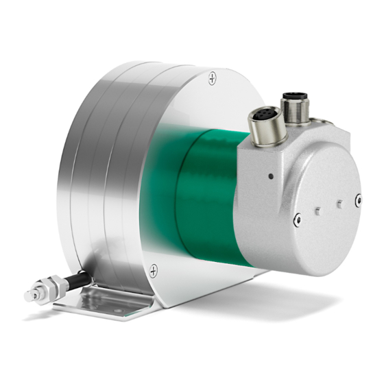
SFA-5000-FD
SFA-10000-FD
• 5000 mm & 10000 mm draw-wire encoder
• Integrated 25 bit absolute multiturn encoder
• Programmable resolution down to 24 µm
• Cable and M12 connectors options
• DeviceNet interface, "Group 2 only server" devices
Suitable for the following models:
SFA-5000-FD
•
SFA-10000-FD
•
Lika Electronic
User's guide
•
Tel. +39 0445 806600
General Contents
Preliminary information
Mounting instructions
Electrical connections
Quick reference (using RSNetWorx)
DeviceNet interface
Setup
Default parameters table
•
info@lika.biz
10
14
18
27
48
80
84
•
www.lika.biz
Advertisement
Table of Contents

Related Manuals for Lika SFA-5000-FD


Summary of Contents for Lika SFA-5000-FD
-
Page 1: User's Guide
User's guide Smart encoders & actuators SFA-5000-FD SFA-10000-FD • 5000 mm & 10000 mm draw-wire encoder • Integrated 25 bit absolute multiturn encoder • Programmable resolution down to 24 µm • Cable and M12 connectors options • DeviceNet interface, “Group 2 only server” devices... - Page 2 Tous droits réservés. This document and information contained herein are the property of Lika Electronic s.r.l. and shall not be reproduced in whole or in part without prior written approval of Lika Electronic s.r.l. Translation, reproduction and total or partial modification (photostat copies, film and microfilm included and any other means) are forbidden without written authorisation of Lika Electronic s.r.l.
-
Page 3: Table Of Contents
General contents User's guide................................. 1 General contents............................. 3 Subject index..............................7 Typographic and iconographic conventions..................... 9 Preliminary information..........................10 1 Safety summary............................11 1.1 Safety......................................11 1.2 Electrical safety..................................11 1.3 Mechanical safety................................12 2 Identification............................. 13 3 Mounting instructions..........................14 3.1 Overall dimensions................................14 3.2 Mounting instructions..............................15 3.3 Useful information................................16 3.4 Maintenance..................................17... - Page 4 Bus off....................................45 12 Offset value................................46 13 Velocity value................................46 14 Velocity format.................................46 15 Dip switch..................................46 16 Data Tx in POLL mode............................46 17 Data Tx in COS/Cyclic mode..........................47 18 Alarm flags..................................47 19 Delta for COS................................47 20 Auto-save parameters............................47 6 DeviceNet interface..........................48 6.1 EDS file.....................................48 6.2 Communication messages...............................48 6.3 I/O Messages (Msg group 1)............................50...
- Page 5 03-01-01 Node Address............................61 03-01-02 Baud rate..............................61 03-01-03 Bus-off interrupt............................61 03-01-04 Bus-off counter............................61 03-01-05 Allocation information........................62 6.5.3 Class 05h: Connection Object..........................63 05-Inst-01 Connection status..........................63 05-Inst-02 Instance type............................63 05-Inst-03 TransportClass_trigger........................63 05-Inst-04 Produced connection ID........................63 05-Inst-05 Consumed connection ID........................63 05-Inst-06 Initial comm. Characteristics......................63 05-Inst-07 Produced connection size........................64 05-Inst-08 Consumed connection...
- Page 6 7 Setup................................80 7.1 Read and set parameters..............................80 7.1.1 P2P Master/Slave connection (without I/0 msg)...................80 7.1.2 Reading the position 23-01-03 Position value (in the “Object dictionary”)........80 7.1.3 Setting 23-01-13 Preset value..........................81 7.1.4 Saving the parameters..............................81 7.1.5 Closing the Master/Slave connection.........................82 7.2 Setting the Cyclic mode without velocity........................82 7.2.1 P2P Master/Slave connection..........................82 7.2.2 Setting 05-Inst-09 Expected packet rate for Cyclic mode (milliseconds)..........82...
-
Page 7: Subject Index
Subject index 23-01-66 Data Tx in Poll mode.........77 23-01-67 Data Tx in COS/Cyclic mode....77 01-01-01 Vendor-ID............58 23-01-68 Auto-save parameters......78 01-01-02 Device type............58 2B-01-01 Acknowledge timer........79 01-01-03 Product code..........58 2B-01-02 Retry Limit.............79 01-01-04 Revision............58 2B-01-03 Connection Instance of COS....79 01-01-05 Status...............58 01-01-06 Serial number..........59 01-01-07 Product name..........60 Alarm flags................47... - Page 8 Owned...................58 Scaling function control..........39 Service not supported............53 Supported alarms.............45 Physical number of revolutions.........45 Physical resolution/revolution........44 Position.................37 Too much data..............53 Position sensor type............38 Total measuring range...........41 Preset value................43 Velocity format..............46 Resource unavailable............53 Velocity value..............46...
-
Page 9: Typographic And Iconographic Conventions
Typographic and iconographic conventions In this guide, to make it easier to understand and read the text the following typographic and iconographic conventions are used: parameters and objects both of the device and the interface are coloured in GREEN; • alarms are coloured in RED;... -
Page 10: Preliminary Information
Preliminary information This guide is designed to provide the most complete and exhaustive information the operator needs to correctly and safely install and operate the SFA-5000 and SFA-10000 absolute draw-wire encoders with DeviceNet interface. The cable pulling mechanism integrates a 13 x 12 bit absolute multiturn encoder (13 bits = singleturn resolution = 8,192 cpr;... -
Page 11: Safety Summary
failure to comply with these precautions or with specific warnings elsewhere in this manual violates safety standards of design, manufacture, and intended use of the equipment; Lika Electronic assumes no liability for the customer's failure to comply with these requirements. 1.2 Electrical safety ... -
Page 12: Mechanical Safety
SFA-5000 • SFA-10000 DeviceNet 1.3 Mechanical safety Install the device following strictly the information in the “3 - Mounting instructions” section on page 14; mechanical installation has to be carried out with stationary mechanical parts; do not disassemble the encoder; ... -
Page 13: Identification
Information is listed in the delivery document too. Please always quote the order code and the serial number when reaching Lika Electronic for purchasing spare parts or needing assistance. For any information on the technical characteristics of the product refer to the technical catalogue. -
Page 14: Mounting Instructions
SFA-5000 • SFA-10000 DeviceNet Mounting instructions WARNING Installation, electrical connection and maintenance operations must be carried out by qualified personnel only, with power supply disconnected. Mechanical components must be in stop. 3.1 Overall dimensions Values are expressed in mm MAN SFA_5000_10000_FD E 1.0.odt Mounting instructions 14 of 88... -
Page 15: Mounting Instructions
SFA-5000 • SFA-10000 DeviceNet 3.2 Mounting instructions Fasten the draw-wire unit onto a fixed support using three M4 screws 1; • remove the safety wire that pins the end of the measuring wire during • transport; fix the end of the measuring wire to the moving unit using the provided •... -
Page 16: Useful Information
200 mm (7.874”), the maximum number of turns is 25 for SFA-5000 and 50 for SFA-10000. EXAMPLE 1 (23-01-0E Scaling SFA-5000-FD-8192-PG using the physical resolution function control = 00) Stroke per turn of the drum = 200 mm (7.874”) -
Page 17: Maintenance
SFA-5000 • SFA-10000 DeviceNet Number of information = 204,800 EXAMPLE 2 (23-01-0E Scaling SFA-10000-FD-8192-M12 using a custom resolution function control = 01) Stroke per turn of the drum = 200 mm (7.874”) 23-01-2A Hardware counts per revolution, physical resolution per turn = 13 bits = 8,192 cpr 23-01-2B Hardware number of turns, number of physical revolutions = 12... -
Page 18: Electrical Connections
SFA-5000 • SFA-10000 DeviceNet Electrical connections WARNING Installation, electrical connection and maintenance operations must be carried out by qualified personnel only, with power supply disconnected. Mechanical components must be in stop. 4.1 Connection cap WARNING Do not remove or mount the connection cap with power supply switched ON. Damage may be caused to internal components. - Page 19 SFA-5000 • SFA-10000 DeviceNet To remove the connection cap loosen the two M3 screws 1. Please be careful when you disconnect the internal connector. Always replace the connection cap at the end of the operation. Take care in re- connecting the internal connector. Tighten the screws 1 using a tightening torque of approx.
-
Page 20: Connection Cap With Pg Gland (Cable Output)
SFA-5000 • SFA-10000 DeviceNet 4.2 Connection cap with PG gland (cable output) Cable output versions (...-PG order code) are fitted with two PG9 cable glands for BUS IN and BUS OUT connections as well as for power supply. The bus cables can be connected directly to the terminal connectors located by each cable gland. -
Page 21: Connection Cap With M12 Connectors
SFA-5000 • SFA-10000 DeviceNet 4.3 Connection cap with M12 connectors Connector output versions (...-M12 order code) are fitted with two M12 connectors with pin-out in compliance with DeviceNet standard. Therefore you can use standard DeviceNet cordsets and patchcords commercially available. For a complete list of the available cordsets and patchcords please refer to the product datasheet (“Accessories”... -
Page 22: Ground Connection
Lika's EC- pre-assembled cables are fitted with shield connection to the connector ring nut in order to allow grounding through the body of the device. Lika's E- connectors have a plastic gland, thus grounding is not possible. If metal connectors are used, connect the cable shield properly as recommended by the manufacturer. -
Page 23: Setting The Baud Rate: Dip A
SFA-5000 • SFA-10000 DeviceNet 4.6 Setting the baud rate: DIP A WARNING Power supply must be turned off before performing this operation! The baud rate must be set using DIP A dip-switches: Switch off the unit and set the binary value of the transmission rate considering that: ON=1, OFF=0. -
Page 24: Setting The Node Address: Dip B
SFA-5000 • SFA-10000 DeviceNet 4.7 Setting the node address: DIP B WARNING Power supply must be turned off before performing this operation! The node number must be set via hardware using DIP B dip-switches. Allowed addresses range between 0 and 63. The default address is 1. Set the node address in binary value: ON=1, OFF=0 used used... -
Page 25: Setting The Rt Bus Termination
SFA-5000 • SFA-10000 DeviceNet 4.8 Setting the RT bus termination WARNING Power supply must be turned off before performing this operation! A bus termination resistance is provided inside the connection cap and must be activated as line termination if the encoder is at the ends of the transmission line (i.e. -
Page 26: Diagnostic Leds
SFA-5000 • SFA-10000 DeviceNet 4.9 Diagnostic LEDs Two diagnostic LEDs located in the connection cap are designed to show the operating or fault status of the DeviceNet interface and the system as well. NS Led Network Status LED: this LED shows the status of the communication network. -
Page 27: Quick Reference (Using Rsnetworx)
5.1 Import EDS file DeviceNet draw-wire encoders are supplied with their own EDS file SFA.eds, it can be downloaded at the address www.lika.biz > PRODUCTS > ROTARY ENCODERS > DRAW-WIRE UNITS (DRAW-WIRE) > ABSOLUTE. EDS file must be installed in the Master device. - Page 28 SFA-5000 • SFA-10000 DeviceNet Press the Browse... button to browse through the folders and select the .eds file to be installed; finally press the Next > button to continue. Then, follow the remaining steps to complete the EDS wizard. MAN SFA_5000_10000_FD E 1.0.odt Quick reference (using RSNetWorx)28 of 88...
-
Page 29: Adding A Node To The Project
5.2 Adding a node to the project In the Hardware pane of the RSNetworx window, open the directory tree and select DeviceNet\Vendor\Lika Electronic SNC\Generic Device; drag the required module SFA-xxxxx-FD to the Graph tabbed page on the right. 5.3 Encoder parameters configuration Double-click the encoder icon in the Graph tabbed page and open the Properties window. - Page 30 SFA-5000 • SFA-10000 DeviceNet Open the General tabbed page of the Properties window and set the node address in the Address box. MAN SFA_5000_10000_FD E 1.0.odt Quick reference (using RSNetWorx)30 of 88...
- Page 31 SFA-5000 • SFA-10000 DeviceNet Open the Parameters page of the Properties window if you need to read, set and save the encoder parameters. 16 Data Tx in POLL mode, 17 Data Tx in Please pay particular attention to COS/Cyclic mode 20 Auto-save parameters attributes.
- Page 32 SFA-5000 • SFA-10000 DeviceNet EXAMPLE Parameter 16: 16 Data Tx in POLL mode = “Position Value + Velocity” Parameter 17: 17 Data Tx in COS/Cyclic mode = ”Position Value” Set the scanner module parameters accordingly: For any further information on the scanner module parameters refer to the “5.5 Using the scanner module“...
-
Page 33: Saving The Parameters With Rsnetworx
SFA-5000 • SFA-10000 DeviceNet 5.4 Saving the parameters with RSNetWorx Properties window allows you to set device parameters. After this operation is carried out, data is stored in the RAM memory only. In case of “Reset node”, “Node restore” power off, parameters will be lost. -
Page 34: Using The Scanner Module
To manage I/O data using the scanner module, right-click the scanner icon and open the Properties window; if requested, upload the configuration. Open the Scanlist tabbed page. Select Lika device in the Available Devices > pane on the left and move it to the Scanlist pane on the right pressing the button. - Page 35 SFA-5000 • SFA-10000 DeviceNet Now, set the Input Size value in both panes Polled and Change of State / Cyclic according to 16 Data Tx in POLL mode 17 Data Tx in COS/Cyclic mode values respectively (see the encoder parameters in the “5.6 Parameters“ section on page 37).
- Page 36 SFA-5000 • SFA-10000 DeviceNet EXAMPLE In the following example: 16 Data Tx in POLL mode = Position value + velocity; 17 Data Tx in COS/Cyclic mode = Position value. Polled messages: Variables Bytes Input Position value Velocity value COS messages: Variables Bytes Input...
-
Page 37: Parameters
Please note that the encoder's linear resolution can be read also in the order code next to the rotary resolution. Refer to the product datasheet. EXAMPLE 1 Let's suppose that we are using the physical resolution of the SFA-5000-FD- 4 Scaling function control 8192-PG draw-wire encoder (the attribute = 0). -
Page 38: Position Sensor Type
Linear position value = transmitted position * linear resolution Linear position value = 123 * 0.024 = 2.952 mm = 2,952 µm EXAMPLE 2 Let's suppose that we are using the SFA-5000-FD-8192-PG draw-wire encoder. (5 Measuring The singleturn resolution is set to the custom value of 4,000 cpr units/rev = 4000). -
Page 39: Scaling Function Control
SFA-5000 • SFA-10000 DeviceNet 4 Scaling function control If this attribute is disabled (OFF = 00), the device uses the physical resolution 8 Physical resolution/revolution 9 Physical number of values (see the revolutions attributes); if it is enabled (ON = 01), it uses the custom resol ution 5 Measuring units/rev 6 Total measuring range set in the... - Page 40 SFA-5000 • SFA-10000 DeviceNet 8 Physical per revolution in the encoder identification label and the resolution/revolution attribute). Default = 8,192 (min. = 1, max. = 8,192) WARNING When you set a new value next to the 5 Measuring units/rev attribute, please 6 Total measuring range always check also the attribute value and be sure...
-
Page 41: Total Measuring Range
SFA-5000 • SFA-10000 DeviceNet 6 Total measuring range WARNING 4 Scaling function control This attribute is active only if the attribute is set to (8 Physical ”=1”; otherwise it is ignored and the system uses the physical values resolution/revolution 9 Physical number of revolutions) to calculate the position information. - Page 42 SFA-5000 • SFA-10000 DeviceNet EXAMPLE We install the following draw-wire encoder: SFA-5000-FD-8192-M12. The physical values are: Stroke per turn of the drum = 200 mm (7.874”) Physical resolution per turn = 13 bits = 8,192 cpr Max. number of physical revolutions = 4,096 revolutions Total physical resolution = 25 bits = 33 554 432 information Physical linear resolution = 0.024 mm = 24 µm...
-
Page 43: Preset Value
SFA-5000 • SFA-10000 DeviceNet In this case you will obtain several 20,000 information sections following each other all along the whole measuring length. The position information will be from 0 to 19,999; then again from 0 to 19,999 and so on. 19,997 19,998 19,999 19,997 19,998 19,999 ←... -
Page 44: Physical Resolution/Revolution
SFA-5000 • SFA-10000 DeviceNet When you set the 7 Preset value and then execute the preset setting, the system saves the current encoder position in the 12 Offset value attribute. It follows that the transmitted value and the 7 Preset value are the same as read position - 12 Offset value... -
Page 45: Physical Number Of Revolutions
SFA-5000 • SFA-10000 DeviceNet This attribute is intended to show the number of physical distinguishable steps per each revolution provided by the hardware (physical singleturn resolution). 5 Measuring If you want to set a custom singleturn resolution see the units/rev attribute on page 39. -
Page 46: Offset Value
SFA-5000 • SFA-10000 DeviceNet 12 Offset value As soon as you activate the preset, the current position value of the encoder is saved on this attribute. The offset value is then used in the preset function in order to calculate the encoder position value to be transmitted. To zero set the value in this attribute you must upload the factory default values (see the 15h Restore Service code on page 66). -
Page 47: Data Tx In Cos/Cyclic Mode
SFA-5000 • SFA-10000 DeviceNet 17 Data Tx in COS/Cyclic mode This parameter is meant to set which input data is sent when the Change Of State (COS) / Cyclic mode connection is enabled. Allowed values: Position value (0, default value) Position value + velocity (1) Default = 0 (min. -
Page 48: Devicenet Interface
SFA-5000 • SFA-10000 DeviceNet DeviceNet interface Lika draw-wire encoders are “Group 2 only server” devices and do not support UCMM messages. For any omitted information refer to the “Open DeviceNet Vendor Association” documents or visit www.odva.org. 6.1 EDS file DeviceNet draw-wire encoders are supplied with their own EDS file SFA.eds, it can be downloaded at the address www.lika.biz >... - Page 49 Config. messages (see section 6.3) (see section 6.4.4) Close connection (see section 6.4.3) NOTE Lika encoders accept only one P2P connection at a time. Simultaneous or multiple P2P connections are rejected. MAN SFA_5000_10000_FD E 1.0.odt DeviceNet interface 49 of 88...
-
Page 50: I/O Messages (Msg Group 1)
SFA-5000 • SFA-10000 DeviceNet 6.3 I/O Messages (Msg group 1) I/0 messages are used by Lika devices to send position and velocity values. The “Message-ID” shows how the message is transmitted. Position: CAN-ID 4 CAN Data bytes 9…6 5…0 Byte 0... -
Page 51: Explicit Messages (Msg Group 2)
SFA-5000 • SFA-10000 DeviceNet 6.4 Explicit Messages (Msg group 2) These messages are used to: perform a duplicate MAC-ID check (see the “6.4.1 Duplicate MAC-ID check“ section on page 52); send error messages (see the “6.4.2 Error messages“ section on page 53); ... -
Page 52: Duplicate Mac-Id Check
SFA-5000 • SFA-10000 DeviceNet 6.4.1 Duplicate MAC-ID check This function is used to check, when a device is connected to the DeviceNet network, whether its serial number, node-ID and vendor-ID are single (univocal) in the network. Message structure: CAN-ID bit 10 MAC-ID 7 CAN Data bytes Byte... -
Page 53: Error Messages
SFA-5000 • SFA-10000 DeviceNet 6.4.2 Error messages These messages are meant to warn about device faults. Message structure: Byte bit7 bit6 bit5 bit4 bit3 bit2 bit1 bit0 Master MAC-ID R/R=1 Service Code = 14h General error code Specific service error code General error codes General Status Code... -
Page 54: Object Does Not Exist
SFA-5000 • SFA-10000 DeviceNet was expected. Object does not exist The object specified does not exist in the device. Invalid parameter A parameter associated with the request was invalid. This code is used when a parameter does not meet the requirements of this specification and/or the requirements defined in an Application Object Specification. -
Page 55: Explicit Messages Connection
SFA-5000 • SFA-10000 DeviceNet 6.4.3 Explicit Messages Connection These messages are meant to open and close P2P connections between Master and Slave. This is necessary to allow the Slave both to communicate process data using “I/O Messages” and communicate or change parameters using “Data transfer”... -
Page 56: Message Data Transfer
SFA-5000 • SFA-10000 DeviceNet 6.4.4 Message data transfer These messages are meant to set, read, save or restore configuration parameters. Data transfer request: Byte bit7 bit6 bit5 bit4 bit3 bit2 bit1 bit0 Master MAC-ID R/R=0 Service Code Class ID Instance ID Attribute ID 5…7 Data byte... -
Page 57: Object Dictionary
SFA-5000 • SFA-10000 DeviceNet 6.5 Object dictionary In the following pages the objects implemented are listed and described as follows: Class-Instance-Attribute Object name [var, access] Class, instance and attribute are expressed in hexadecimal notation. Var: data type variable USINT: unsigned single integer 8 bit (1 byte) UINT: unsigned integer 16 bit (2 bytes) UDINT: unsigned double integer 32 bit (4 bytes) -
Page 58: Class 01H: Identity Object
SFA-5000 • SFA-10000 DeviceNet 6.5.1 Class 01h: Identity Object This object provides identification and general information on the device. Supported Service codes: 0Eh = Get_Attribute_Single: used to read the connection class attribute value. Supported Instances: 01h = Explicit Message 01-01-01 Vendor-ID [UINT, ro] Identification of the vendor by its own number. -
Page 59: Extended Device Status
SFA-5000 • SFA-10000 DeviceNet device has been configured to do something different than the “out–of–box” default. This shall not include configuration of the communications. Reserved Reserved, shall be 0 Extended device status Bits are defined as follows: 0000 Self-Testing or Unknown Firmware Update in Progress At least one faulted I/O connection No I/O connections established... -
Page 60: Product Name
SFA-5000 • SFA-10000 DeviceNet 01-01-07 Product name [SHORT_STRING, ro] Default = 05 4C 49 4B 41 20h = “LIKA” MAN SFA_5000_10000_FD E 1.0.odt DeviceNet interface 60 of 88... -
Page 61: Class 03H: Devicenet Object
SFA-5000 • SFA-10000 DeviceNet 6.5.2 Class 03h: DeviceNet Object This DeviceNet Object is meant to provide the configuration and status of the physical node connected to the DeviceNet network. Supported Service code: 0Eh = Get_Attribute_Single: used to read connection class attribute value. 10h = Set_Attribute_Single: used to write connection class attribute value. -
Page 62: Allocation Information
SFA-5000 • SFA-10000 DeviceNet 03-01-05 Allocation information [UINT, ro] byte: “Allocation choice”: indicates which “Predefined Master/Slave Connections” is active. byte: “Master’s MAC-ID” contains the MAC-ID of the device that has allocated the “Predefined Master/Slave Connection”. The FFh value means that the “Predefined Master/Slave Connection” has not been allocated (no communication active). -
Page 63: Class 05H: Connection Object
SFA-5000 • SFA-10000 DeviceNet 6.5.3 Class 05h: Connection Object The Connection Class allocates and manages the internal resources associated to both “I/O Messages” and “Explicit Messaging Connections”. Supported Service code: 0Eh = Get_Attribute_Single: used to read connection class attribute value. 10h = Set_Attribute_Single: used to write connection class attribute value. -
Page 64: 05-Inst-07 Produced Connection Size
SFA-5000 • SFA-10000 DeviceNet 05-Inst-07 Produced connection size [UINT, ro] Maximum number of bytes transmitted in this connection. 05-Inst-08 Consumed connection size [UINT, ro] Maximum number of bytes received in this connection. 05-Inst-09 Expected packet rate [UINT, rw] This attribute is meant to set the time between two subsequent “I/O message” transmissions (Transmission Trigger Timer) and the Inactivity/Watchdog Timer. -
Page 65: 05-Inst-11 Production Inhibit Time
SFA-5000 • SFA-10000 DeviceNet 05-Inst-11 Production inhibit time [UINT, ro] Default = 00h: no inhibit time NOTE To save the parameters execute the “Save parameters” function (see “7.1.4 Saving the parameters“ in the “7.1 Read and set parameters“ section on page 81). -
Page 66: Class 23H: Position Sensor Object
SFA-5000 • SFA-10000 DeviceNet 6.5.4 Class 23h: Position Sensor Object This class is meant to describe the objects used by the device to calculate the transmitted position values. Supported Service code: 05h = Reset: resets all parameter values to the factory default values (without saving them on flash memory). - Page 67 Please note that the encoder's linear resolution can be read also in the order code next to the rotary resolution. Refer to the product datasheet. EXAMPLE 1 Let's suppose that we are using the physical resolution of the SFA-5000-FD- 23-01-0E Scaling function control 8192-PG draw-wire encoder (the attribute = 0).
-
Page 68: 23-01-0B Device Type
SFA-5000 • SFA-10000 DeviceNet Thus the linear position value will be as follows: Linear position value = 1,569 * 0.05 = 78.45 mm = 78,450 µm 23-01-0B Device type [UINT, ro] Type of device. 0002h: multiturn absolute rotary encoder. 23-01-0C Code sequence [BOOL, rw] 23-01-0C Code sequence attribute sets whether the position value output by... -
Page 69: Resolution Per Revolution
SFA-5000 • SFA-10000 DeviceNet revolution 23-01-11 Total measuring range attributes that are consistent with the physical values. WARNING Every time you enable the scaling function and/or change the scaling values (see 23-01-10 Resolution per revolution 23-01-11 Total measuring range attributes) then you are required to set a new preset value (see the 01-13 Preset value attribute) and finally save the new parameters (execute the “Save parameters”... -
Page 70: Total Measuring Range
SFA-5000 • SFA-10000 DeviceNet 23-01-11 Total measuring range = 33 554 432 = 8,192 (cpr) * 4,096 (rev.) 23-01-10 Resolution per Let's set a new singleturn resolution, for instance: revolution = 360 cpr. 23-01-11 Total measuring range If we do not change the value at the same time, we will get the following result: (23-01-11 Total... - Page 71 23-01-10 Resolution per revolution, the above setting is not allowed. EXAMPLE We install the following draw-wire encoder: SFA-5000-FD-8192-M12. The physical values are: Stroke per turn of the drum = 200 mm (7.874”) Physical resolution per turn = 13 bits = 8,192 cpr Max.
- Page 72 SFA-5000 • SFA-10000 DeviceNet Let's suppose that we need a tenth of a millimetre linear resolution in the specific installation. 23-01-0E Scaling function control Enable the scaling function: • attribute = 01 23-01-10 Resolution per revolution Custom resolution per turn = •...
-
Page 73: Preset Value
SFA-5000 • SFA-10000 DeviceNet 19,997 19,998 19,999 19,997 19,998 19,999 ← → max. measuring length NOTE To avoid counting errors we recommend values which are power of 2 (2 : 2, 4, 23-01-10 Resolution per …, 2048, 4096, 8192,…) to be set next to the revolution 23-01-11 Total measuring range attributes. - Page 74 SFA-5000 • SFA-10000 DeviceNet Encoder Master (2 message received) CAN-ID 3 Data byte 403+(ID<<3) Encoder Master (parameter value accepted) CAN-ID 3 Data byte 403+(ID<<3) EXAMPLE Let's take a look at the following example to better understand the preset 23-01-13 Preset function and the meaning and use of the related attributes: value...
-
Page 75: Delta For Cos
SFA-5000 • SFA-10000 DeviceNet NOTE If the scaling function is disabled (see the 23-01-0E Scaling function control 23-01-13 Preset value attribute), the must be less than or equal to the “Total hardware resolution” - 1 (23-01-2A Hardware counts per ... -
Page 76: 23-01-2B Hardware Number Of Turns
SFA-5000 • SFA-10000 DeviceNet (23-01-10 Resolution per revolution 23-01-11 Total measuring range) to calculate the position information. This attribute is intended to show the number of physical distinguishable steps per each revolution provided by the hardware (physical singleturn resolution). If you want to set a custom singleturn resolution see the 23-01-10 Resolution per revolution attribute on page 69. -
Page 77: 23-01-2E Alarm Flags
SFA-5000 • SFA-10000 DeviceNet broken (cable disconnected? Voltage drop? ...). 23-01-2E Alarm flags [BOOL, ro] It indicates that a fault occurred and an alarm has been triggered, see the 23-01-2D Supported alarms previous attribute. 23-01-33 Offset [DINT, ro] As soon as you activate the preset, the current position value of the encoder is saved on this attribute. -
Page 78: Auto-Save Parameters
SFA-5000 • SFA-10000 DeviceNet 01: Position value + velocity 23-01-68 Auto-save parameters [BOOL, rw] 0 = No: new parameters are not saved on EPROM automatically. To save new values, the Class Instance Editor must be used (default value; see the “5.4 Saving the parameters with RSNetWorx“... -
Page 79: Class 2Bh: Acknowledge Handler Object
SFA-5000 • SFA-10000 DeviceNet 6.5.5 Class 2Bh: Acknowledge Handler Object This class is meant to manage the receipt of acknowledgement messages. Supported Service code: 0Eh = Get_Attribute_Single: used to read connection class attribute value. 10h = Set_Attribute_Single: used to write connection class attribute value. Supported Instance: 01h = Explicit Message 2B-01-01 Acknowledge timer [UINT, rw]... -
Page 80: Setup
SFA-5000 • SFA-10000 DeviceNet Setup Here follow some examples of parameters reading and setting; data exchange between Master and Slave devices is highlighted. A generic “ID” value is used to indicate the encoder address; Master address is always assumed to be 0. All values are written in hexadecimal notation. -
Page 81: Setting 23-01-13 Preset Value
SFA-5000 • SFA-10000 DeviceNet 7.1.3 Setting 23-01-13 Preset value Master Encoder (1 message) CAN-ID 8 Data byte preset 404+(ID<<3) … Encoder Master (1 message received) CAN-ID 3 Data byte 403+(ID<<3) Master Encoder (2 message) CAN-ID 4 Data byte preset 404+(ID<<3) …... -
Page 82: Closing The Master/Slave Connection
SFA-5000 • SFA-10000 DeviceNet 7.1.5 Closing the Master/Slave connection Master Encoder CAN-ID 5 Data byte 406+(ID<<3) Encoder Master CAN-ID 3 Data byte 403+(ID<<3) 7.2 Setting the Cyclic mode without velocity 7.2.1 P2P Master/Slave connection Master Encoder (request) CAN-ID 6 Data byte 406+(ID<<3) - Page 83 SFA-5000 • SFA-10000 DeviceNet 05-Inst- From now on, the encoder sends I/0 messages at the interval set in the 09 Expected packet rate attribute until the connection will be closed or the 05-Inst-09 Expected packet rate attribute will be modified. Encoder ...
-
Page 84: Default Parameters Table
SFA-5000 • SFA-10000 DeviceNet Default parameters table Parameter list Default value 1 = count up 3 Counting direction information when pulling the cable out 4 Scaling function control 0 = DISABLED 5 Measuring units/rev 8192 6 Total measuring range 33 554 432 7 Preset value 14 Velocity format 0 = STEPS/S... - Page 85 This page intentionally left blank...
- Page 86 This page intentionally left blank...
- Page 87 This page intentionally left blank...
- Page 88 EDS file Document release Release date Description version 19/04/2018 1st issue 1.002 Lika Electronic Via S. Lorenzo, 25 • 36010 Carrè (VI) • Italy Tel. +39 0445 806600 Fax +39 0445 806699 info@lika.biz • www.lika.biz...
Need help?
Do you have a question about the SFA-5000-FD and is the answer not in the manual?
Questions and answers