Table of Contents
Advertisement
Quick Links
Smart encoders & actuators
SFAM1-05000
SFAM2-10000
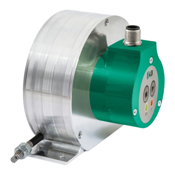
Absolute draw-wire encoder with analogue output
•
Voltage or current signals
•
Programmable via keys
•
Max. measuring length 5000 (196.85") or 10000 mm (393.7")
•
Cable or cable with integral M12 connector
•
Suitable for the following models:
SFAM1-05000-TI12-...
•
SFAM1-05000-TV12-...
•
SFAM1-05000-TV22-...
•
SFAM2-10000-TI12-...
•
SFAM2-10000-TV12-...
•
SFAM2-10000-TV22-...
•
Lika Electronic
User's guide
•
Tel. +39 0445 806600
Absolute draw-wire encoder with analogue output
General Contents
Preliminary information
Safety summary
Identification
Mechanical installation
Electrical connection
TEACH-IN procedure
•
info@lika.biz
12
18
•
www.lika.biz
5
6
8
9
Advertisement
Table of Contents

Related Manuals for Lika SFAM1-05000


Summary of Contents for Lika SFAM1-05000
-
Page 1: User's Guide
User's guide Smart encoders & actuators SFAM1-05000 SFAM2-10000 Absolute draw-wire encoder with analogue output Absolute draw-wire encoder with analogue output • Voltage or current signals • Programmable via keys • Max. measuring length 5000 (196.85”) or 10000 mm (393.7”) •... - Page 2 Tous droits réservés. This document and information contained herein are the property of Lika Electronic s.r.l. and shall not be reproduced in whole or in part without prior written approval of Lika Electronic s.r.l. Translation, reproduction and total or partial modification (photostat copies, film and microfilm included and any other means) are forbidden without written authorisation of Lika Electronic s.r.l.
-
Page 3: Table Of Contents
General contents User's guide......................................1 General contents.....................................3 Typographic and iconographic conventions........................4 Preliminary information................................5 1 Safety summary............................. 6 1.1 Safety.....................................6 1.2 Electrical safety.................................6 1.3 Mechanical safety..............................7 2 Identification............................8 3 Mechanical installation........................9 3.1 Overall dimensions..............................9 3.2 Mounting instructions............................10 3.3 Useful information..............................11 3.4 Maintenance................................11 4 Electrical connection.......................... -
Page 4: Typographic And Iconographic Conventions
Typographic and iconographic conventions In this guide, to make it easier to understand and read the text the following typographic and iconographic conventions are used: parameters are coloured in GREEN; • alarms are coloured in RED; • states are coloured in FUCSIA. •... -
Page 5: Preliminary Information
SFAM1-05000 / SFAM2-10000 is available in the following range of voltage and current analogue signals: 0 to 5V (...-TV12-... order code);... -
Page 6: Safety Summary
• elsewhere in this manual violates safety standards of design, manufacture, and intended use of the equipment; Lika Electronic assumes no liability for the customer's failure to comply • with these requirements. 1.2 Electrical safety Turn OFF the power supply before connecting the device;... -
Page 7: Mechanical Safety
SFAM1-05000 TA • SFAM2-10000 TA - minimize noise by connecting the shield and/or the connector housing and/or the frame to ground. Make sure that ground is not affected by noise. The connection point to ground can be situated both on the device side and on user’s side. -
Page 8: Identification
Information is listed in the delivery document too. Please always quote the order code and the serial number when reaching Lika Electronic. For any information on the technical characteristics of the product refer to the technical catalogue. -
Page 9: Mechanical Installation
SFAM1-05000 TA • SFAM2-10000 TA Mechanical installation WARNING Installation has to be carried out by qualified personnel only, with power supply disconnected and mechanical parts compulsorily in stop. 3.1 Overall dimensions Values are expressed in mm MAN SFAM1_05000_SFAM2_10000 TA E 1.3 Mechanical installation... -
Page 10: Mounting Instructions
SFAM1-05000 TA • SFAM2-10000 TA 3.2 Mounting instructions Fasten the draw-wire unit onto a fixed support using three M4 screws • remove the transport safety wire that pins the end of the measuring • wire; fix the end of the measuring wire to the moving unit using the provided •... -
Page 11: Useful Information
50 mm is the low limit overrun value; the analogue range is scaled in a 5000 mm travel for SFAM1-05000; in a 10000 mm travel for SFAM2-10000. Positive counting by unwinding the wire. -
Page 12: Electrical Connection
SFAM1-05000 TA • SFAM2-10000 TA Electrical connection WARNING Electrical connection has to be carried out by qualified personnel only, with power supply disconnected and mechanical parts compulsorily in stop. 4.1 Cable and connectors connections Function A8 cable M12 5-pin +Iout / +Vout... -
Page 13: M12 5-Pin Connector Specifications
SFAM1-05000 TA • SFAM2-10000 TA 4.3 M12 5-pin connector specifications Male Frontal side A coding 4.4 Connection of the shield For signals transmission always use shielded cables. The cable shielding must be connected properly to the metal ring nut 3 of the connector in order to ensure a good earthing through the frame of the device. -
Page 14: Output Circuits
SFAM1-05000 TA • SFAM2-10000 TA user’s side. The best solution to minimize the interference must be carried out by the user. You are advised to provide the ground connection as close as possible to the encoder. 4.6 Output circuits 4.6.1 Analogue current output description •... -
Page 15: Input Signals Description
SFAM1-05000 TA • SFAM2-10000 TA 4.6.4 Input signals description +13Vdc +30Vdc, 0Vdc: encoder power supply; • START: the same as the START key; it is active at HIGH logic level • (voltage greater than 10V must be applied). For any further information on using the START ... -
Page 16: Fault Output Connected To A Relay
SFAM1-05000 TA • SFAM2-10000 TA 4.6.5.2 Fault output connected to a relay Imax = 50mA R1 = 47 Figure 2 EXAMPLE Vdc = +24V I = 30mA (current needed to energize a small relay coil) R2 = 750... -
Page 17: Recommended Circuit
SFAM1-05000 TA • SFAM2-10000 TA 4.7 Recommended circuit 4.7.1 Current analogue output 4.7.2 Voltage analogue output MAN SFAM1_05000_SFAM2_10000 TA E 1.3 Electrical connection 17 of 24... -
Page 18: Teach-In Procedure
SFAM1-05000 TA • SFAM2-10000 TA TEACH-IN procedure The TEACH-IN function allows to easily and intuitively set (by means of two keys or, as an alternative, two external signals) both the furthermost points in the travel of an axis, then the available analogue range will be scaled automatically within the set limits. - Page 19 SFAM1-05000 TA • SFAM2-10000 TA NOTE You are allowed to set the START position first and then the END position of the travel by pressing the START key first and then the STOP key (see the Figure below); otherwise you can do the opposite, i.e. you can set the END position first and then the START position of the travel by pressing the STOP ...
-
Page 20: Overrun Function
SFAM1-05000 TA • SFAM2-10000 TA NOTE Should the START position (START ) be the same as the end position (STOP ), in other words, you do not change the axis position when you press the keys, unit resets and restores the factory default settings (see the “5.4 Restoring the factory default... -
Page 21: Overrun Function With Tv12 And Tv22 Order Codes
SFAM1-05000 TA • SFAM2-10000 TA 5.2.2 Overrun function with TV12 and TV22 order codes In the TV12 and TV22 order code encoders, the OVERRUN function operates as described for TI12 order code encoders but the overtravel position is defined by keeping for a certain space (number of revolutions) the minimum / maximum output value available in the analogue range;... -
Page 22: Restoring The Factory Default Settings
50 mm (they are calculated starting from wire fully wound) and the analogue value in the first 50 mm is the low limit overrun value; the analogue range is scaled in a 5000 mm travel for SFAM1-05000; in a 10000 mm travel for SFAM2-10000. Positive counting by unwinding the wire. -
Page 23: Times And Functions
SFAM1-05000 TA • SFAM2-10000 TA from the initial position), the initial position has been set by pressing the START key During the inverted TEACH-IN procedure (i.e. starting from the final position), the final position has been set Flash by pressing the STOP key 5.6 Times and functions... - Page 24 Default setting instructions updated (“5.4 Restoring 13.10.2015 the factory default settings” section) 06.11.2015 New membrane keys 13.02.2023 New product name, new order code Lika Electronic Via S. Lorenzo, 25 • 36010 Carrè (VI) • Italy Tel. +39 0445 806600 Fax +39 0445 806699 info@lika.biz...
Need help?
Do you have a question about the SFAM1-05000 and is the answer not in the manual?
Questions and answers