Table of Contents
Advertisement
Advertisement
Table of Contents
Troubleshooting

Related Manuals for PerkinElmer OilExpress 4


Summary of Contents for PerkinElmer OilExpress 4
- Page 1 MOLECULAR SPECTROSCOPY OilExpress 4 Oil Condition Monitoring System User’s Guide...
- Page 2 The information contained in this document is subject to change without notice. Except as specifically set forth in its terms and conditions of sale, PerkinElmer makes no warranty of any kind with regard to this document, including, but not limited to, the implied warranties of merchantability and fitness for a particular purpose.
-
Page 3: Table Of Contents
Mechanical Hazards ...................22 Environment ....................22 Use of Flammable Solvents and Samples ............24 Material Safety Data Sheets ................26 Overview of the OilExpress 4 System ............27 System Specifications ..................28 Liquid Autosampler ...................29 Connection Panel ..................30 Varispan Pipetting Arm and VersaTips ............30 System Liquid Container(s) ................31... - Page 4 Troubleshooting .................... 128 Spares and Consumables ................141 Appendices ..................... 145 Appendix 1: Decontamination ................. 146 Appendix 2: WEEE Instructions for PerkinElmer Products ......... 147 Appendix 3: Liquid Handling ................148 Appendix 4: Fluid Path Materials ..............149 Index ......................150...
-
Page 5: Introduction
Introduction... -
Page 6: About This Manual
66 to learn how to run an analysis and modify some basic software parameters. NOTE: Refer to the on-screen Help system available from the Help menu in the OilExpress 4 software for full information about using the software. -
Page 7: Conventions
UPPERCASE text refers to keys on the PC keyboard. “+” is used to show that you have to press two keys at the same time, for example, ALT+F. Part Numbers All eight-digit numbers are PerkinElmer part numbers unless stated otherwise. Notes, Warnings and Cautions Three terms, in the following standard formats, are also used to highlight special circumstances and warnings. - Page 8 8 . OilExpress 4 System User's Guide We use the term CAUTION to inform you about situations that could CAUTION result in serious damage to the instrument or other equipment. Details about these circumstances are in a box like this one.
- Page 9 Introduction . 9 We use the term WARNING to inform you about situations that could result in personal injury to yourself or other persons. Details about these circumstances are in a box like this one. WARNING Warning (Warnung) Bedeutet, daß es bei Nichtbeachten der genannten Anweisung zu einer Verletzung des Benutzers kommen kann.
-
Page 10: Oilexpress 4 Oil Condition Monitoring Systems
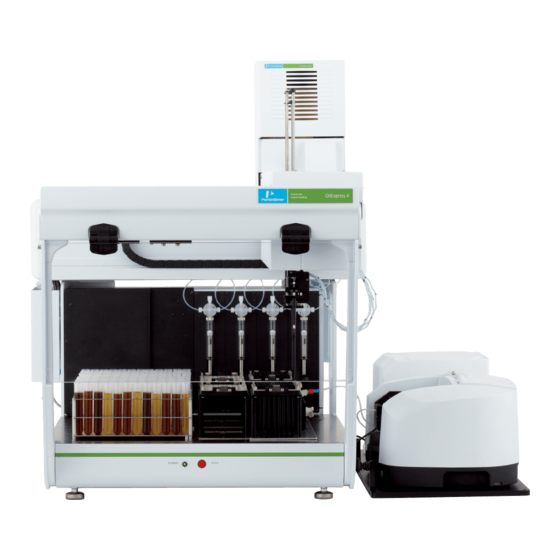
10 . OilExpress 4 System User's Guide OilExpress 4 Oil Condition Monitoring Systems The OilExpress 4 Oil Condition Monitoring Systems (Figure 1) are optimized for the high- throughput FT-IR analysis of in-service lubricant samples for additive depletion, contamination and degradation. -
Page 11: Introduction To Oil Analysis By Infrared Spectroscopy
Introduction to Oil Analysis by Infrared Spectroscopy The OilExpress 4 System is an automated system that uses infrared (IR) analysis to monitor additive depletion, contaminant build-up and base-stock degradation of in-service lubricants and hydraulic fluids. A range of analysis methods for measuring these parameters are supplied, including standard methods for Mineral Oils, Synthetic Oils, the Joint Oil Analysis Program (JOAP) and ASTM. -
Page 12: Degradation Products
12 . OilExpress 4 System User's Guide Degradation Products Oxidation Oil exposed to oxygen at elevated temperature will oxidize to a variety of compounds, the majority of which are carbonyl compounds, including carboxylic acids. Carboxylic acids contribute to the acidity of the oil, depleting the basic additives present and contributing to corrosion. -
Page 13: Common Contaminants
Introduction . 13 Antioxidant Pheonolic antioxidant compounds are often used in turbine lubricants. Depletion of antioxidant is followed by a rapid increase in the rate of oxidation. Common Contaminants Soot Soot particles result from the incomplete combustion of fuel and, since they are too small to be removed by the filter, remain suspended in the oil. - Page 14 A collection of direct-trending FT-IR oil analysis methods for several oil types was developed as part of the US Army, Navy and Air Force Joint Oil Analysis Program (JOAP). These methods are widely used and are supported by OilExpress 4; a complete list is given in Analysis Methods on page 16.
-
Page 15: References
The standard methods shipped with OilExpress 4 do not present results in terms of analyte concentrations. Rather, they are expressed in terms of absorbance, usually in units of absorbance per centimeter. -
Page 16: Analysis Methods Provided
16 . OilExpress 4 System User's Guide Analysis Methods Provided The OilExpress 4 System ships with a set of default analysis methods that will appear in the Running an Analysis Analysis drop-down list on the Samples screen (refer to on page 81). -
Page 17: Warnings And Safety Information
Warnings and Safety Information... -
Page 18: Overview
This advice is intended to supplement, not supersede, the normal safety codes in the user's country. It is also a supplement to the PerkinElmer standard Safety and Health Policy. The information provided does not cover every safety procedure that should be practiced. -
Page 19: Oilexpress 4 System Safety Summary
OilExpress 4 System for the relevant compliance information. In routine use, the OilExpress 4 System poses virtually no risk to you. If you take some simple, common-sense precautions, you can make sure that you maintain the continued safe operation of the OilExpress 4 System. -
Page 20: General Safety
20 . OilExpress 4 System User's Guide General Safety If the system is used in a manner not specified by the manufacturer, the protection provided by the instrument may be impaired. Only use the OilExpress 4 System indoors and under the following conditions: Temperature: 15 °C to 35 °C... - Page 21 Only connect peripheral equipment that meets the requirements of IEC 61010-1, IEC 60950 or equivalent standards. · Ensure that you have sufficient power outlets for your OilExpress 4 system (Table 3). Table 3 Power outlets required for OilExpress 4 systems Product...
-
Page 22: Mechanical Hazards
Ensure that there are no overhanging shelves, and no water pipes or faucets that could · leak onto the OilExpress 4 System. The OilExpress 4 system must be installed on a flat and level bench (such as · part number 5085685), free from vibrations or mechanical shocks. - Page 23 The external waste container must be placed either beneath the instrument or nearby · on the floor. The waste container must be lower than the fluid control module(s). · Observe local and national regulations when disposing of waste from the OilExpress 4 System.
-
Page 24: Use Of Flammable Solvents And Samples
24 . OilExpress 4 System User's Guide Use of Flammable Solvents and Samples The OilExpress 4 products require solvent for the use of the system, either as system liquid or as diluent. Heptane is the recommended system liquid for FT-IR analysis. For dual-mode FT-IR/Oil Dilution systems you will have a second solvent, such as V-Solv ICP solvent or odorless kerosene for oil dilution. - Page 25 If a serious spillage occurs, then remove the deck plates to access the drip trays. However, removing the deck plates may invalidate the deck CAUTION calibration, which could lead to an autosampler collision. We recommend that you contact your PerkinElmer Service Representative to check if recalibration is required.
-
Page 26: Material Safety Data Sheets
You can search for up-to-date copies of safety data sheets on hazardous materials, such as ZnSe, used in PerkinElmer products from the Technical Resources section of the PerkinElmer website. The MSDS information is available in a range of languages, and includes data items required in specific national, supra-national and state jurisdictions. -
Page 27: Overview Of The Oilexpress 4 System
Overview of the OilExpress 4 System... -
Page 28: System Specifications
28 . OilExpress 4 System User's Guide System Specifications Sample Viscosity Range 1–900 cSt* Sample Throughput 15W40 Oil (120 cSt)*: Single-spectrometer system 70 per hour Dual-spectrometer system (DUO) 100 per hour Sample Volume 800 µL Typical Solvent Volume (per sample) 3.0 mL for 15W40 oil... -
Page 29: Liquid Autosampler
Overview of the OilExpress 4 System . 29 Liquid Autosampler The OilExpress 4 System uses a liquid autosampler to enable the sampling of approximately 70 samples per hour with a single-spectrometer system, or 100 samples per hour with a DUO (dual-spectrometer) system. -
Page 30: Connection Panel
Figure 5 Autosampler connection panel The other connections on the panel are for communications between optional accessories for the autosampler that are not relevant for your OilExpress 4 System. If you require more information, please contact your PerkinElmer Customer Care Representative. -
Page 31: System Liquid Container(S)
Overview of the OilExpress 4 System . 31 For FT-IR analysis using OilExpress 4 software, two of the VersaTips are dedicated to aspirating samples for analysis using wide-bore disposable tips (VersaTips 1 and 3). The other two are dedicated to dispensing system liquid, for example to clean the flow cell (Figure 6). - Page 32 32 . OilExpress 4 System User's Guide For FT-IR analysis using the OilExpress 4 System the recommended system liquid is heptane. If you have a dual-purpose system and will be using WinPREP software for oil dilution, you will require a second system liquid container containing V-Solv ICP solvent or odorless kerosene.
-
Page 33: Labware Configurations
Figure 7 shows the correct positioning of sample racks (on the left deck) and tip boxes (on the right deck) for the 96-position rack on an OilExpress 4 XL System (FT-IR-Only mode). The used tip boxes are shown in the darker shade. The injection station is also shown at the far right. -
Page 34: Sample Racks
34 . OilExpress 4 System User's Guide Details of all the Deck Layouts are provided in the OilExpress 4 on-screen Help. You can current access the topic that describes the Deck Layout for your configuration from several dialogs in OilExpress 4 software. When an Initialization dialog is displayed at the start of an... - Page 35 OilExpress can also be configured to support other sample racks in some cases. This requires support from PerkinElmer engineering to create adaptor plates and labware files, as well as service support to configure a custom layout for the autosampler. For more information on setting up a custom layout, consult your PerkinElmer Product Specialist or Service Representative.
- Page 36 The adaptor plate consists of two parts that are connected together by two fastening screws that also function as locating pins on the autosampler deck. The correct configuration depends on the type of OilExpress 4 System and the location on the deck. Refer to Figure 11 and Table 5.
- Page 37 The 32-position rack holds 4 oz bottles (or 2 oz bottles) in four columns of eight samples. One 32-position rack can be installed on the OilExpress 4 System, while up to three can be installed on the OilExpress 4 XL System.
-
Page 38: Tip Boxes
Figure 13 32-position rack adaptor plate Tip Boxes Two sets of tip boxes are required for use with the OilExpress 4 System (Figure 14). One contains the clean disposable tips that are used to aspirate samples. The other should be empty and is used by the autosampler for depositing used tips. - Page 39 Source Tip Box Adaptor Plate (OilExpress 4 with 96-position rack only) If you have an OilExpress 4 (standard) system and are using the 96-position sample rack, then an adaptor plate is required to position the clean tips correctly on the autosampler deck (Figure 16).
-
Page 40: Injection Station
40 . OilExpress 4 System User's Guide Reset Tip Boxes During autosampler use, OilExpress 4 software keeps a count of the clean tips used and the used tip box positions filled. If the software identifies that the tip boxes need to be refilled, or if you click the Review/Reset Tip Boxes button on an Initialization dialog, the Reset Tip Boxes dialog is displayed (Figure 17). - Page 41 Overview of the OilExpress 4 System . 41 The components of the injection station are labeled in Figure 18. Fill cups are used to dispense oil or solvent to the flow cell through tubing connected to the lower flow cell port.
-
Page 42: Autosampler Safety Shield And Stop Button
When you click OK, the autosampler will not move until you perform an action in either OilExpress 4 or WinPREP software. You may need to use the Flush controls on the Autosampler Control screen to clean and air dry the fluid lines and flow cell, before you start a new analysis. -
Page 43: Spectrometer Module
If you spill liquid in the sample compartment, wipe it up quickly. The Spectrum Two supplied with the OilExpress 4 System has an internal, automated filter wheel, which can be used to insert a reference material in the beam path. The filter wheel provided contains a polystyrene sample, an NG11 Schott Glass reference, and a methane cell (for use in the AVI Calibration). -
Page 44: Sample Shuttle
44 . OilExpress 4 System User's Guide Sample Shuttle The sample shuttle (Figure 21) is used to move the flow cell in and out of the beam, enabling the measurement of a background or a sample spectrum, as required. This automated... -
Page 45: Liquid Presence Sensor
(to minimize unwanted fringing effects) spacer to give a nominal pathlength of 0.1 mm. You can calibrate the Pathlength Calibration utility in OilExpress 4 software, which using a Quant method to calculate the pathlength. A Quant method is supplied with your system, but you can configure the test to use your own method. -
Page 46: Connections On The Spectrometer
46 . OilExpress 4 System User's Guide Figure 24 Liquid presence sensor indicating no sample detected The sensor is connected to the rear of the FCM, and is powered by the FCM (not the sample shuttle). Electrical NOTE: If the LED is not lit, check that the sensor is connected to the FCM. Refer to... - Page 47 When the spectrometer is on the Power ON LED on the front of the instrument will be lit green. The spectrometer is connected via a USB connection (Figure 27) to a powered USB hub, which is in turn connected to the PC running OilExpress 4. USB port USB 2.0 cable spectrometer connection Figure 27 USB 2.0 cable connector and USB port...
-
Page 48: Fluid Control Module
48 . OilExpress 4 System User's Guide Fluid Control Module The fluid control module (FCM) is a vacuum control system used to manage the movement of system liquid and samples through the system after delivery to the fill cup by the autosampler (Figure 28). -
Page 49: Connections On The Fcm
Overview of the OilExpress 4 System . 49 During the system initialization at the start of an analysis, some checks are run on the FCM(s). If a problem is identified, contact your PerkinElmer Service Representative. A log file (one per FCM) is saved to: C:\Program Data\PerkinElmer\OilExpress\FCMPerformance. - Page 50 The fluid control module is connected by USB cable to the powered USB hub, which is in turn connected to the PC running OilExpress 4 software. NOTE: DO NOT connect the USB cable, or the powered USB hub, to the USB expansion card...
- Page 51 Overview of the OilExpress 4 System . 51 Fluid connections on the FCM The fluid connections on the rear of the FCM are shown in Figure 31 (shown with the connectors installed in the mounting block). Fluid tubing connections on the rear of the FCM connect the upper (outlet) port on the flow cell to the waste transfer container (WTC) in the FCM, and the WTC to the external waste liquid container.
-
Page 52: Waste Container
FCM(s) so that any vapor condensing in the line will drain to the container. NOTE: The system liquid container available with the OilExpress 4 system is 2 L (part number L9004516) and the waste container is 5 L (part number L9004517). -
Page 53: Spectrometer And Fcm Mounting System
Two pins on the mounting system connect with the ports on the autosampler base. For the OilExpress 4 XL systems, a spacer is required between the autosampler and the mounting system so that the spectrometer is clear of the moving parts of the autosampler (Figure 34). -
Page 54: Ultrasonic Liquid Level Sensor Bar (Optional)
This means that you cannot simply change your sample rack type in the OilExpress 4 software to use the Ultrasonic Liquid Level Sensor Bar with another rack type: you will need to contact your PerkinElmer Service Representative. - Page 55 In the example in Figure 36, two sample racks are required for the analysis of 192 samples on an OilExpress 4 XL System. The software first prompts you to load Sample Rack 1 and Sample Rack 2 (containing samples 97 to 192) at the rear of the deck and then click Continue.
-
Page 56: Ultrasonic Height Sensing Errors Dialog
Ultrasonic Height Sensing Errors dialog is displayed in OilExpress 4 software (Figure 38). NOTE: The dialog will not list any sample positions that were defined as Do Not Analyze in the Samples table, or those for which a custom height was entered. -
Page 57: Oil Dilution
FT-IR analysis without moving your original samples. Refer to the OilExpress 4 software on-screen Help for more information about allowed deck layouts for the dual FT-IR analysis / oil dilution mode. -
Page 58: Overview Of The Ft-Ir Analysis Procedure
58 . OilExpress 4 System User's Guide Overview of the FT-IR Analysis Procedure Single-spectrometer System NOTE: This procedure is appropriate for either a single-spectrometer system or a DUO (dual-spectrometer) system using the lower spectrometer only. The procedure for a DUO using the upper spectrometer only is similar, but Fill Cup 2 is connected to the flow cell and VersaTip 4 is used for cleaning. - Page 59 Overview of the OilExpress 4 System . 59 8. The spectrometer collects a background spectrum. The autosampler status is Idle. The spectrometer status is Background. 9. The autosampler moves to the first available clean tip in the first available clean tip box and loads a disposable tip on VersaTips 1 and 3.
- Page 60 LED changes from red to green. The time taken for the liquid to reach the sensor is used by the OilExpress 4 software to calculate parameters, such as the time required for the FCM to draw the sample into the flow cell (if required) and the adaptive cleaning settings.
- Page 61 18. The syringe dispenses system liquid from VersaTip 2 into Fill Cup 1 and through the fluid lines for a number of wash cycles. The wash cycles may be defined by the OilExpress 4 system (using Adaptive Cleaning) or by the user on the Autosampler Setup dialog (Figure 45).
-
Page 62: Dual-Spectrometer (Duo) System
62 . OilExpress 4 System User's Guide 24. The autosampler moves to the first available clean tip and loads a disposable tip on VersaTips 1 and 3. These are collected from positions 2 and 4. 25. The autosampler returns to the injection station and positions VersaTip 2 over Fill Cup 1, and the fluid lines and flow cell are washed as in Step 13. - Page 63 Overview of the OilExpress 4 System . 63 7. If Prime autosampler on initialization was selected on the Batch Initialization dialog, the prime starts. Refer to Priming the System on page 74 for more information about priming the system. The autosampler status is Priming. The spectrometer status is Idle.
- Page 64 LED changes from red to green. The time taken for the liquid to reach the sensor is used by the OilExpress 4 software to calculate parameters, such as the time required for the FCM to pump the sample into the flow cell and the adaptive cleaning settings.
- Page 65 Overview of the OilExpress 4 System . 65 17. The autosampler arm moves the disposable tips to the first available empty waste tip location, and the two used tips are dropped into positions 1 and 3. 18. The autosampler moves to the first available clean tip and loads a disposable tip on VersaTips 1 and 3 from the next two available positions.
- Page 66 The wash cycles may be defined by the OilExpress 4 system (using Adaptive Cleaning) or by the user on the Autosampler Setup dialog (Figure 45). If using Adaptive Cleaning, the wash cycles are calculated for each sample independently.
-
Page 67: Getting Started With Oilexpress 4
Getting Started with OilExpress 4... -
Page 68: Overview
68 . OilExpress 4 System User's Guide Overview This section describes some basic functionality of OilExpress 4 software. It will show you how you can: · Log in to OilExpress 4 software · Familiarize yourself with the OilExpress 4 software environment ·... -
Page 69: Starting Oilexpress 4 Software
– and fluid control module(s) are connected to mains power and switched on. 2. From the Start menu select All Programs; the PerkinElmer Applications group; the OilExpress 4 sub-group and then the OilExpress 4 application. Double-click the OilExpress 4 shortcut icon on the desktop. -
Page 70: The Oilexpress 4 Window
70 . OilExpress 4 System User's Guide The OilExpress 4 Window The OilExpress 4 software environment is shown in Figure 39. Figure 39 OilExpress 4 Window Menus Main Screen Toolbar Status Bar Navigation Bar Menus The Menus (A) are at the top of the workspace. These include the File menu, which can be... - Page 71 Getting Started with OilExpress 4 . 71 Navigation Bar The Navigation Bar (C), contains shortcuts to key functions of OilExpress 4 software. The item selected will be displayed in the Main Screen (Figure 41). For example, you can use the Process Controls to access the Batch screen, which enables you to set up the options for your batch, or the Samples screen, which enables you to add sample data and select a method for the analysis.
-
Page 72: Oilexpress 4 On-Screen Help System
72 . OilExpress 4 System User's Guide OilExpress 4 On-screen Help System Use the OilExpress 4 Help system to find further information about using OilExpress 4 software to set up and run your oil analyses. To open the Help file, select Contents from the Help menu. This menu also includes links to the PerkinElmer website (PerkinElmer on the Web) and information about the software (About). -
Page 73: Sample Preparation
If you are using the Ultrasonic Liquid Level Sensor Bar to measure the sample heights, the height at which samples are aspirated from your samples will be determined by OilExpress 4 software. The minimum level for samples depends on your sample container. Refer to the OilExpress 4 on-screen Help for more information. -
Page 74: Priming The System
Refer to Handling on page 148 for more information about liquid handling in the OilExpress 4 System. We recommend that you prime the system once a day (before collecting data), or whenever you observe air in the fluid lines. - Page 75 For this, you can use the Prime option on the Autosampler Control screen in OilExpress 4 (Figure 44). Figure 44 Prime option on the Autosampler Control dialog Autosampler Control Refer to the topic in the OilExpress 4 on-screen Help for more information.
-
Page 76: Defining The Sampling Heights
If you have the optional Ultrasonic Liquid Level Sensor Bar installed, the option Use Ultrasonic Height Sensing will be selected by default, and the OilExpress 4 software will determine the appropriate height from which to aspirate each sample. The minimum level for Ultrasonic Liquid Level Sensor Bar samples depends on your sample container. - Page 77 The sample height information entered in the Samples screen will be saved and can be viewed in the Database Results in the Results Browser. NOTE: For more information about the Samples table, refer to the OilExpress 4 on-screen Help. Running an...
-
Page 78: Saving Spectra, Exporting Spectra And Reporting
78 . OilExpress 4 System User's Guide Saving Spectra, Exporting Spectra and Reporting In OilExpress 4 software, data is saved to a database. There are various features in the software to help you present your data outside OilExpress 4. Exporting Spectra You can export spectra as PerkinElmer-format (*.sp), ASCII (*.asc), comma-separated values... -
Page 79: Exporting Results
Getting Started with OilExpress 4 . 79 Exporting Results CSV Export during data collection If you select the option Enable export to CSV File, then you can configure the system to export sample results to a comma separated values (CSV) file. When the CSV export is activated, a new line is appended to the CSV output file as each sample analysis is completed. -
Page 80: Reporting
80 . OilExpress 4 System User's Guide Reporting The Analysis Reports options enable you to print a report, either after an individual sample analysis or at the end of a batch (Figure 49). Figure 49 Analysis Reports and Checks Reports on the Reporting Options Dialog Reports are displayed automatically as part of System Checks and the Pathlength Calibration. -
Page 81: Running An Analysis
Running an Analysis This section will run through the sample analysis from starting OilExpress 4 software to completing a batch. When OilExpress 4 software starts, a new batch is already displayed on the Batch screen. 1. Enter the Number of samples to be analyzed. - Page 82 82 . OilExpress 4 System User's Guide 6. Click in the first empty cell below Sample ID. 7. Type in a name for the first sample. This could be the same as an identifying label on the sample container. You may find it useful to include the rack number or position (for example, Sample 1_1).
- Page 83 105 for more information. NOTE: For more information about reference spectra, including how to collect a new reference, and details of the analysis methods provided, refer to the OilExpress 4 on-screen Help. 12. Click on a suitable reference spectrum to select it, and then click OK.
- Page 84 Refer to on page 75 and the topic the OilExpress 4 on-screen Help for more details on setting the fixed heights. 14. If the analysis needs to correct the results for sample dilution, type a value for the Dilution Factor.
- Page 85 Sample 1_2, Sample 1_3 ..18. If you want OilExpress 4 to print a report of the results, or to output your spectra to a folder as *.sp files, then select Reporting Options from the File menu.
- Page 86 Boxes. The Reset Tip Boxes dialog is displayed. OilExpress 4 software retains a count of the tips used from the previous analysis. 22. If you are continuing the tip count from a previous analysis, check that actual number of clean tips (or empty used tip positions) in each tip box on your deck agrees with the information in the dialog.
- Page 87 You can load a previously saved batch that has not been run to completion. Refer to the Batch topic in the OilExpress 4 on-screen Help. You can also import batch and sample information from an existing batch, a suitably formatted comma separated variable (CSV) file Batch Import and or from an oil dilution sample information file (SIF file).
-
Page 88: Modifying Scan Settings
NOTE: For more information about AVI, refer to page 89. For more information about the options available on these tabs, and which options are Scan Settings relevant for your OilExpress 4 System spectrometer, refer to the topic and related topics in the OilExpress 4 on-screen Help. -
Page 89: Absolute Virtual Instrument (Avi)
Getting Started with OilExpress 4 . 89 Absolute Virtual Instrument (AVI) AVI Correction AVI correction is enabled on the Advanced tab of the Instrument Settings Properties dialog (Figure 51). AVI correction can only be applied if an AVI Calibration has been set up for the current instrument and sampling configuration. -
Page 90: Avi Calibration
AVI calibration will have been performed by your PerkinElmer Service Representative during your OilExpress 4 System installation. However, after any spectrometer maintenance such as the replacement of the source, or if you have replaced the sample shuttle, the AVI calibration should be repeated. - Page 91 Getting Started with OilExpress 4 . 91 3. Ensure that there is no obstruction in the sample compartment, and then click Continue. The sample shuttle moves to the background position and the background spectrum is collected. When the scan is complete, the methane cell in the automated filter wheel is rotated into the beam path.
-
Page 92: System Validation
System Checks check that your system – that is, instrument and accessory – are fit-for- purpose. These are run from OilExpress 4 software. You are advised to run the Cell Contamination check daily, or after each batch of samples if you are analyzing samples with unusually high soot levels. -
Page 93: System Checks
96 for cleaning instructions for your flow cell. NOTE: The addition of the OilExpress 4 System Liquid Additive (part number N9308354) to the system liquid has been found to reduce soot build-up on the flow cell windows. Refer to OilExpress 4 System Liquid Additive on page 32. - Page 94 At the end of the tests a report containing the results will be displayed. It will be printed if Reporting the Checks Reports option was selected on the Reporting Options dialog. Refer to on page 80 for more information. NOTE: Refer to the OilExpress 4 on-screen Help for more information about running System Checks.
-
Page 95: Maintenance And Troubleshooting
Maintenance and Troubleshooting... -
Page 96: Flow Cell Maintenance
96 . OilExpress 4 System User's Guide Flow Cell Maintenance NOTE: The addition of the OilExpress 4 System Liquid Additive to the system liquid has been found to reduce soot build-up on the flow cell windows when analyzing engine oils OilExpress 4 System Liquid Additive with high soot contents (>0.5%). -
Page 97: Removing And Installing The Flow Cell
Ensure that any cleaning solutions will not damage the ZnSe windows. Also ensure that they are compatible with the materials used in the CAUTION OilExpress 4 system fluid path. Refer to Appendix 4: Fluid Path Materials on page 149. Never use strong acids or bases, or oxygen-containing solvents such as aldehydes, ketones or ethers, with the system without first checking compatibility, as these liquids may cause immediate and severe damage. - Page 98 98 . OilExpress 4 System User's Guide 6. Disconnect the tubing to the lower port of the flow cell from the injection station (Figure 53). Turn the lock hub on the Luer-lok connector approximately one half-turn counter- clockwise, until loose, and then pull to remove from the port on the injection station.
- Page 99 Maintenance and Troubleshooting . 99 8. Lift the clip up, and gently loosen the upper port tubing so that it is no longer trapped in the groove (Figure 55). Figure 55 Shuttle hinged arm securing clip open 9. Rotate the hinged arm slightly clockwise, while carefully releasing the lower port tubing from the groove, to move the liquid presence sensor clear of the slide holder.
- Page 100 100 . OilExpress 4 System User's Guide 11. Place the flow cell on the bench (Figure 57). Do not to stretch the tubing between the FCM and the upper port of the flow cell. You may find it easier to disconnect the tubing from the FCM.
- Page 101 Maintenance and Troubleshooting . 101 3. Maintaining pressure, screw the blue nut connector clockwise with your other hand until the tubing is secured (Figure 59). Figure 59 Securing tubing to the upper port of the flow cell The connector should be initially hand screwed onto the flow cell until finger-tight. Then apply an additional tightening of 1/8 of a turn using the 5.5 mm wrench supplied (part number 09923411).
- Page 102 102 . OilExpress 4 System User's Guide 12. Reconnect the liquid presence sensor to the rear of the FCM. 13. Reconnect the autosampler, spectrometer(s) and FCM(s) to the mains power supply. 14. Start OilExpress 4 software. 15. If replacing an existing flow cell, ensure that the correct Flow Cell Serial No is selected on the Spectrometer Setup dialog.
-
Page 103: Disassembling The Flow Cell For Deep Cleaning
Spares and Consumables available separately – refer to on page 141. Alternatively, you can arrange for your flow cell to be refurbished by PerkinElmer (Flow Cell Refurbishment L1272490R). Contact your PerkinElmer Customer Care representative for more information. Take care not to touch the zinc selenide (ZnSe) windows when handling the flow cell, or wear protective gloves. - Page 104 104 . OilExpress 4 System User's Guide Orientation of washers on screw Back of cell Former Rubber gasket Back window (both faces smooth) Spacer (wedged, with thicker end at bottom) Front window (engraved side facing inwards) PTFE gasket Front of cell Figure 60 Disassembling or assembling the flow cell 3.
-
Page 105: Empty Cell Spectrum
OilExpress 4 System. Empty Cell Spectrum The empty cell spectrum was collected for each flow cell installed with your OilExpress 4 System by your PerkinElmer Service Representative. However, after refurbishing your flow cell, or before using a new flow cell, you will need to collect a new empty cell reference spectrum. - Page 106 The empty cell spectrum is collected using a Macro in Spectrum software. NOTE: The macro was installed to the C:\pel_data\macros folder during your OilExpress 4 System installation, and has the file name OilExpress Empty Cell.prc. To collect a new empty cell spectrum: 1.
- Page 107 Maintenance and Troubleshooting . 107 4. If required, enter your User name and Password, and then click OK. These are the same user name and password that you use with OilExpress 4 software. The Instrument Connection dialog is displayed. NOTE: If Auto-Connect is enabled, then Spectrum will automatically connect to a spectrometer and the Instrument Connection dialog is not displayed.
- Page 108 108 . OilExpress 4 System User's Guide The OilExpress Empty Cell prompt screen is displayed. This provides information about the steps you need to follow to collect the spectrum. 7. Click Continue. The Sample table is displayed, containing one sample. The Sample ID for the empty cell spectrum is entered automatically, but you can change it if you want –...
-
Page 109: Calibrating The Pathlength Of The Flow Cell
Refer to on page 105. Your PerkinElmer Service Representative will have calibrated your flow cell(s) as part of the OilExpress 4 system installation. However, after any flow cell maintenance, or if you purchase a new cell, the pathlength must be calibrated if you want to correct for differences in pathlength between flow cells. - Page 110 CELLPATH.md) were generated for 0.1 mm ZnSe cells. The Pathlength - squalane.qmd method is selected by default. The Pathlength - squalane.qmd method requires OilExpress 4 Pathlength Calibration Fluid −1 (part number N9308377), and the calibration should be run using 4 cm resolution .
- Page 111 For information about the numbering of racks for your specific deck layout, refer to the OilExpress 4 on-screen Help. 7. If you want to flush the fluid lines and flow cell using the system liquid at the end of the calibration, select the Clean fluid lines after calibration check box.
- Page 112 112 . OilExpress 4 System User's Guide The default Lower and Upper thresholds are 0.09 and 0.12, respectively. The default Residual Threshold, if applicable, is 25. 9. When you are satisfied that you have the correct parameters, click OK. 10. Click Start to begin the calibration.
- Page 113 The residual ratio value should decrease. · The flow cell is clean. · The beam of the spectrometer is not obstructed. · The cell is mounted correctly in the sample shuttle. If you are unable to resolve the issue, contact your PerkinElmer Service Representative.
-
Page 114: Installing The Flow Cell / Injection Station Fluid Lines
Retain the spare parts for future use. The material and dimensions of the tubing are critical for the correct operation of the OilExpress 4 System. DO NOT alter the lengths. DO CAUTION NOT attempt to use alternative tubing. - Page 115 Maintenance and Troubleshooting . 115 5. Hold the tubing in one hand and push the end of the 650 mm tubing into the upper port of the flow cell, so that the ferrule is pushed up to the inside of the cell. 6.
- Page 116 116 . OilExpress 4 System User's Guide 8. Rotate the hinged arm back into place, carefully feeding the tubing into their respective grooves as you do so (Figure 65). Figure 65 Shuttle hinged arm closed; tubing in grooves 9. Ensure the tubing to the injection station is positioned correctly in the lower groove, and that the tubing to the FCM is positioned correctly in the upper grove.
- Page 117 Maintenance and Troubleshooting . 117 14. Screw the blue nut connector from the tubing from the lower port of the flow cell into a red Luer-lok connector. 15. Connect the tubing from the lower port of the flow cell to the appropriate fill cup on the injection station.
-
Page 118: Autosampler Maintenance
118 . OilExpress 4 System User's Guide Autosampler Maintenance Daily Preventative Maintenance Priming the System We recommend that you Prime the system to remove any residue, deposits or air bubbles Priming daily or whenever you observe air in the syringes or tubing to the VersaTips. Refer to the System on page 74. -
Page 119: Weekly Preventative Maintenance
If you routinely empty the waste container whenever you refill the system liquid container, the waste container will not overflow. NOTE: The system liquid container available with the OilExpress 4 system is 2 L (part number L9004516) and the waste container is 5 L (part number L9004517). - Page 120 120 . OilExpress 4 System User's Guide Inspecting the Fluid Path (Tubing and Syringes) DO NOT attempt to adjust any connections while the autosampler is in operation. Ensure that you wear appropriate protective gloves when handling fluid lines that may contain harmful materials.
-
Page 121: Spectrometer Maintenance
Maintenance and Troubleshooting . 121 Spectrometer Maintenance use the appropriate Replacement Wizard in OilExpress 4 or must Spectrum software to replace the source, desiccant or sample CAUTION compartment windows. During the maintenance procedure, the internal temperature of the instrument is maintained to prevent the ingress and condensation of water vapor, which could damage the optics. -
Page 122: Changing To A Single-Spectrometer System (Duo Systems Only)
122 . OilExpress 4 System User's Guide Changing to a Single-spectrometer System (DUO Systems Only) If you have DUO system and one of your spectrometers or FCM(s) requires maintenance, you can switch to a single-spectrometer system to continue analyzing samples. - Page 123 Maintenance and Troubleshooting . 123 6. Disconnect the tubing to the lower port of the flow cell from the injection station (Figure 70). Turn the lock hub on the Luer-lok connector approximately one half-turn counter- clockwise, until loose, and then pull to remove from the connector on the injection station.
-
Page 124: Installing The Sample Shuttle
124 . OilExpress 4 System User's Guide 10. When you feel the spectrometer come free of the connector, pull the front of the sample shuttle towards you and upwards, clear of the sample compartment (Figure 71). Figure 71 Pull the sample shuttle clear of the sample compartment... - Page 125 Maintenance and Troubleshooting . 125 When the sample shuttle initializes, take care that your fingers, tie, etc. are not trapped by the movement. WARNING NOTE: After any maintenance on the fluid lines, inspect them for leaks before running an analysis or leaving the system unattended.
-
Page 126: Fluid Control Module Maintenance
126 . OilExpress 4 System User's Guide Fluid Control Module Maintenance Clean the outside of the fluid control module (FCM) using a soft cloth dampened with detergent or degreasant. Always perform a patch test on an inconspicuous area. Check the connections on the rear of the FCM for leaks, and tighten the connectors, if required. -
Page 127: Moving The System
Maintenance and Troubleshooting . 127 Moving the System If you move your OilExpress 4 System, we recommend that you contact your PerkinElmer Service Representative to check the autosampler deck calibration before using the system again. -
Page 128: Troubleshooting
128 . OilExpress 4 System User's Guide Troubleshooting Problem Possible Cause Corrective Action Starting OilExpress 4 Software Connecting to spectrometer Spectrometer is not powered on Check that the spectrometer (and – OilExpress 4 fails to shuttle) is connected to the mains... - Page 129 (part number L1050228) Contact your PerkinElmer Service Representative. Supply the log file, if required Start Analysis (from Samples screen) OilExpress 4 fails to connect FCM is not connected to mains Connect FCM to the mains power to the FCM power...
- Page 130 130 . OilExpress 4 System User's Guide FCM fails fit-for-purpose test FCM hardware failure Contact your PerkinElmer Service (continued) Representative Provide the log file for the FCM that failed, if required Refer to Fluid Control Module page 48 Valve or Pump failure –...
- Page 131 Inspecting the Fluid Path Refer to (Tubing and Syringes) on page 120 If you are unable to resolve the issue, contact your PerkinElmer Service Representative Syringe to VersaTip fluid System not primed after Use the Prime button on the lines contain air after priming...
- Page 132 132 . OilExpress 4 System User's Guide FT-IR error – source failure Source must be replaced Run the Source Replacement Spectrometer Wizard. Refer to Maintenance on page 121 FT-IR error – other – Contact your PerkinElmer Service Representative Click Stop Analysis...
- Page 133 Inspecting the Fluid Path Refer to (Tubing and Syringes) on page 120 If you are unable to resolve the issue, contact your PerkinElmer Service Representative FCM hardware failure Contact your PerkinElmer Service Representative Provide the log file for the FCM...
- Page 134 134 . OilExpress 4 System User's Guide Sample not loaded into the Sample was not in correct Check that all sample racks are flow cell during a System position on the autosampler deck located correctly on the deck for Check or Load operation the current system configuration.
- Page 135 Check that the tip boxes are empty. Empty tip boxes, as required. Update the Reset Tip Boxes dialog, as required If this fails to resolve the problem, contact your PerkinElmer Service Representative Arm fails to drop disposable tips Contact your PerkinElmer Service Representative...
- Page 136 136 . OilExpress 4 System User's Guide Click Stop Analysis Liquid is not dispensed Syringe or tubing has a leak or a during a flush (continued) blockage Inspect lines for blockages. Tighten tubing and connections to the syringes Refer to...
- Page 137 Check that the sensor is correctly connected to the rear of the FCM NOTE: The LED does not If this fails to resolve the issue, change to green when contact your PerkinElmer Service the sample reaches the Representative sensor, or is always green...
- Page 138 138 . OilExpress 4 System User's Guide The results obtained for one Air was aspirated with sample Check the sampling heights on the or more properties are (using fixed heights, actual Autosampler Setup dialog, and in unexpected / unacceptable height of sample in container...
- Page 139 Cell Fill sample Check on the Batch Options dialog OilExpress 4 software Results database size greater Use the OilExpress 4 Archive Tool operations are very slow or than 500 MB to archive your database occasionally come to a halt...
- Page 140 140 . OilExpress 4 System User's Guide Empty Cell Spectrum macro Refer to the message box for the Follow the suggestions on the Empty Cell fails repeatedly cause of the failure message box. Refer to Spectrum on page 105 If, after taking any appropriate...
-
Page 141: Spares And Consumables
N9300850 (contains N9308350, N9308351, N9308352, N9308354 and N9308377) FT-IR In-Service Lubricants Control Oil (100 mL) N9308350 OilExpress 4 120 cSt Oil (500 mL) N9308351 OilExpress 4 360 cSt Oil (100 mL) N9308352 OilExpress 4 System Liquid Additive (100 mL) N9308354... - Page 142 Ultrasonic Liquid Level Sensor Bar (field fit – 17 mm tubes) L1610020 Ultrasonic Liquid Level Sensor Bar (field fit – 4 oz bottles) L1610030 OilExpress 4 Single to DUO KBr FT-IR Upgrade L160001E OilExpress 4 Single to DUO ZnSe FT-IR Upgrade L160001F...
- Page 143 Laboratory Bench (80” × 30”, fixed height) 5085685 (accommodates the autosampler, spectrometer, PC, monitor and keyboard) * Contact your PerkinElmer Customer Care Representative for more information. ** Refer to the Spectrum Two User’s Guide (part number L1050228) for a full list of Spectrum Two replacement parts.
- Page 144 144 . OilExpress 4 System User's Guide...
-
Page 145: Appendices
Appendices... -
Page 146: Appendix 1: Decontamination
(8:30 a.m. – 7 p.m. EST ) (+1) 203-925-4602 (outside the USA) Customer Care Canada: 800-561-4646 Customer Care EU: 0800 40 858 (Brussels) 0800 90 66 42 (Monza) If you are located outside of these regions, please call your local PerkinElmer sales office for more information. -
Page 147: Appendix 2: Weee Instructions For Perkinelmer Products
0800 40 858 (Brussels) 0800 90 66 42 (Monza) Products from other manufacturers may also form a part of your PerkinElmer system. These other manufacturers are directly responsible for the collection and processing of their own waste products under the terms of the WEEE Directive. Please contact these manufacturers directly before discarding any of their products. -
Page 148: Appendix 3: Liquid Handling
The aspirate and dispense volumes, aspirate and dispense rates, and air gaps have been optimized and pre-defined for OilExpress 4 FT-IR analysis, and cannot be adjusted by the user. However, if you would like to read a more detailed account of the principles behind this, JANUS®... -
Page 149: Appendix 4: Fluid Path Materials
Appendices . 149 Appendix 4: Fluid Path Materials Ensure that any sample or cleaning materials loaded into the flow cell are compatible with the ZnSe flow cell windows and the materials in the fluid path (Table 6). Never use strong acids or bases, or oxygen-containing solvents such as aldehydes, ketones or ethers, with the system without first checking CAUTION compatibility, as these liquids may cause immediate and severe damage. -
Page 150: Index
150 . Index Index Decontamination ......146 Degradation Products ..... 12 Ester breakdown ......12 32-position Rack ......37 Nitration ........12 Adaptor plate ......38 Oxidation ........12 Sulfate ........12 Direct-Trending ....... 13, 16 96-position Rack ......35 Adaptor plate ...... - Page 151 End of analysis ......136 References ........15 Initialization/Start .....129 Reporting ........80 Start Analysis ......129 Requirements Starting OilExpress 4 ....128 Environment ......22 System Checks/Calibrations ..139 Review/Reset Tip Boxes ....40 Running an Analysis ...... 81 Ultrasonic Liquid Level Sensor Bar .. 54 Unburned Fuel ......
- Page 152 152 . OilExpress 4 System User's Guide Varispan Arm ........ 30 Waste Container ......52 VersaTips ........30 Water ........... 13 WEEE Directive ......147 Windows Start Menu ...... 69...
Need help?
Do you have a question about the OilExpress 4 and is the answer not in the manual?
Questions and answers