GREER Company MicroGuard 586 Operation Manual
Rated capacity indicator system for industrial cranes
Hide thumbs
Also See for MicroGuard 586:
- Manual (75 pages) ,
- Operation/setup manual (44 pages) ,
- Quick manual (2 pages)

Related Manuals for GREER Company MicroGuard 586


Summary of Contents for GREER Company MicroGuard 586
- Page 1 MicroGuard® 586 Rated Capacity Indicator System For Industrial Cranes Operation Manual Consider Yourself Warned™ MicroGuard 586 RCI Operation Manual W458208C 05/11 ®...
-
Page 2: Table Of Contents
Table of Contents Introduction ......................... 3 System Description ......................4 Operator’s Display Console ....................6 Warning Alarm Indicators ....................6 Display Windows ......................6 Push Buttons ......................... 7 System Operation ........................ 8 System Self Test ......................8 Configuration Selection ....................... 9 Normal Operation ...................... -
Page 3: Introduction
Introduction The MicroGuard 586 System is designed for use as an aid to crane operation. ® Note: Do not use this system in place of a properly trained operator who is knowledgeable in safety guidelines, crane capacity information, and the crane manufacturer’s specifications. This manual describes the setup, operation, and troubleshooting of the MICROGUARD®... -
Page 4: System Description
System Description The system, which includes a computer, an operator’s display console, an extension reel, and various cables and sensors; and is designed to measure and display load weight, calculate and display maximum capacity and percent of rated capacity, display code configuration numbers, and warn of an approaching overload or two-block condition for each crane configuration. - Page 5 The computer provides all of the functions necessary to read the system sensors, work out computations, and control the disconnect functions. In order to reliably calculate crane parameters, such as load and rated capacity, and interpret the crane capacity chart and code configuration numbers, information defining the physical characteristics of the crane has been loaded during factory setup.
-
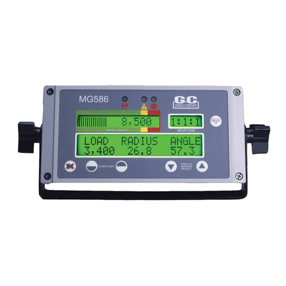
Page 6: Operator's Display Console
Operator’s Display Console Warning/Alarm Indicators Two-Block Pre-Warning Overload and Fault The red two-block lamp will illuminate when a two-block condition occurs (see “Two-Block Warning” on page 12). The yellow pre-warning lamp will illuminate at 90% of rated capacity (see “Approaching Overload” on page 11). -
Page 7: Push Buttons
Push Buttons Setup Alarm Contrast Display Mode Override Select The SETUP key enables the operator to configure the system to match the actual setup of the crane. Codes are present for: • Stowed jib attachments; if no stowed options are available, this code will not appear. •... -
Page 8: System Operation
System Operation System Self-Test When the system is turned on, it goes through a brief self-testing process. All three alarm indicators will light up, all display windows will appear black, and the audible alarm will sound. The information display will then show the crane model and capacity chart number for the system configured. -
Page 9: Configuration Selection
Configuration Selection Configuration selection is required upon system power up; however, it can also be entered anytime by pressing the SETUP key. Note: If no stowed jib options are available, this selection option is skipped. The stages for selection, in no specific order, may include the following: 1. -
Page 10: Normal Operation
Normal Operation Percent of Rated Capacity Rated Capacity Actual Load Boom Angle Boom Length Percent of rated capacity indicates how near the operation is to full capacity and overload. The percent of rated capacity meter progresses to the right as the percentage increases. As long as the meter remains within the normal (green-bordered) zone, the percent of rated capacity is within normal operating limits. -
Page 11: Approaching Overload
Normal Operation (Continued), If the system has any internal faults, it will display “!WARNING! SYSTEM FAULT” in the information window. The specific fault messages can be viewed by pressing the UP ARROW or DOWN ARROW key (see “System Fault Messages” on page 19). WARNING! THE OPERATOR MUST SELECT THE CORRECT CRANE CONFIGURATION FOR EACH SETUP CONFIGURATION CHANGE. -
Page 12: Maximum Capacity And Overload
Maximum Capacity and Overload Overload Lamps When the rated capacity of the crane reaches 100%, the percent of rated capacity meter moves from the caution (yellow-bordered) zone into the warning (red-bordered) zone. The overload lamps will illuminate and an alarm will sound continuously. The message “!WARNING! – OVERLOAD”... -
Page 13: Alarm Override
Alarm Override The alarm override button is used to temporarily disable current audible alarm conditions and to disable the automatic motion cutout. This audible alarm will sound again following any subsequent overload or two- block conditions, or any other alarm conditions. To disable the audible alarm, press the ALARM OVERRIDE (CANCEL) key. -
Page 14: System Care
System Care It is recommended that the system checks be carried out when using the MicroGuard 586 Rated Capacity ® Indicator/Limiter System. 1 Routine Checks and Maintenance Items to Check before Each Shift or Crane Operation: • Extension reel – reel-off cable to boom tip – extension reel cable to computer •... -
Page 15: Routine Checks And Maintenance
2 Routine Checks and Maintenance Reel-Off Cable Reel-Off Cable Check Points: • Carefully examine the reel-off cable for damage. • Fully telescope the boom in and out. When extending or retracting the boom, ensure that the reel-off cable is smoothly fed on and off the extension reel without drooping along the boom or jumping, especially as the boom is telescoped in. -
Page 16: Routine Checks And Maintenance
3 Routine Checks and Maintenance Hydraulic Connections The two hydraulic pressure sensors, mounted in the computer, measure the pressure within each side of the boom hoist cylinder. The pressure sensors are connected to the boom hoist cylinder valve block by two flexible hoses. -
Page 17: Routine Checks And Maintenance
4 Routine Checks and Maintenance Checking the Two-Block Warning Signals and Cutout of Machine Motions The following test activates the anti-two-block warning signals and the valve controlling cut out of crane motions to ensure proper operation. No other pre-existing alarm conditions may be active when performing this test. -
Page 18: Routine Checks And Maintenance
5 Routine Checks and Maintenance Load Test The best way to identify a possible problem in the system is to do a load test. The accuracy of the load test is dependent upon accurate operation of all the sensors in the system and the correct configuration selec- tion. -
Page 19: System Fault Messages
System Fault Messages When the system detects a fault, the red warning lamp will illuminate and the message, "WARNING: SYSTEM FAULT" will flash on the display. When a more serious fault is detected, the mes- sage, "WARNING: SYSTEM OUT OF SERVICE" will flash. To determine the fault, press the UP ARROW or DOWN ARROW key once or twice. - Page 20 System Fault Messages, (Continued) Fault Message Corrective Action Check ATB Wiring This message indicates that there is an Anti Two- Block wiring problem usually due to an electrical short to the boom or a damaged cable. 1. Inspect/ check cabling and connections from computer to extension reel on the side of the boom.
-
Page 21: Extension Reel Voltage Checks
Extension Reel Voltage Checks If problems occur with the two-block alarm operation, angle, or extension sensor, the following chart details voltage checks that may be made within the extension reel. Follow the action column before measuring voltages at the specified points in the voltmeter connection columns. Measure all voltages with a digital voltmeter set to DC volts range. -
Page 22: Computer Internal Status Indicators
Computer Internal Status Indicators Note: Due to differences in computer configurations, the locations of these indicators may vary, as shown below. The computer unit contains 9 LED indicators that provide an aid to checking presence of power supply voltages and communications between the computer and display console. There are 6 power indicators (D8, D10, D11, D13, D14, and D17) and three communications indicators (D7, D9, and D12), all Indicators are bright green light emitting diodes. - Page 23 Computer Internal Status Indicators (Continued), LED Indicator Function Communication Indicator TST0 Battery Power_POS Communication Indicator TST1 +10V COMM (Communications Indicator) +8V2 +5VA +3V3 W458208C 07/2020 MicroGuard 586 RCI Operation Manual ®...
-
Page 24: Computer Replacement
Computer Replacement To remove the computer unit: 1. Place the boom in its rest. 2. Turn off electrical power. 3. Disconnect all electrical connectors from / to the computer. 4. Disconnect hydraulic hose connections from / to the computer. 5. Remove computer from mounting. WARNING! THE HYDRAULIC HOSES CONNECT DIRECTLY TO THE BOOM HOIST CYLINDER. - Page 25 www.dovertwg.com © 2020 TWG. All rights reserved W458208C 07/2020 MicroGuard 586 RCI Operation Manual ®...
Need help?
Do you have a question about the MicroGuard 586 and is the answer not in the manual?
Questions and answers