GREER Company MicroGuard 586 Operation/Setup Manual
Rated capacity indicator/limiter system
Hide thumbs
Also See for MicroGuard 586:
- Manual (75 pages) ,
- Operation manual (25 pages) ,
- Quick manual (2 pages)
Table of Contents
Advertisement
Quick Links
GREER COMPANY
Crane Systems
MicroGuard
586
®
Rated Capacity Indicator/Limiter System
MG-586
!
STOP
SETUP
OK
RATED CAPACITY
SETUP CODE
DISPLAY
CONTRAST
SELECT
Operation/Setup Manual
GREER Company
Page 1 of 44
®
MicroGuard
586 Operation/Setup Manual
1918 East Glenwood Place
W458200 REV C 10/29/02
Santa Ana CA 92705
Advertisement
Table of Contents

Related Manuals for GREER Company MicroGuard 586


Summary of Contents for GREER Company MicroGuard 586
- Page 1 GREER COMPANY Crane Systems MicroGuard ® Rated Capacity Indicator/Limiter System MG-586 STOP SETUP RATED CAPACITY SETUP CODE DISPLAY CONTRAST SELECT Operation/Setup Manual GREER Company Page 1 of 44 ® MicroGuard 586 Operation/Setup Manual 1918 East Glenwood Place W458200 REV C 10/29/02...
-
Page 2: Table Of Contents
Other Displayed Warnings........................... 19 System Care ..............................20-25 Routine Checks and Maintenance........................20-25 Faults ................................... 26 Fault Messages............................26-28 Extension Reel Voltage Checks .......................... 29 GREER Company Page 2 of 44 ® MicroGuard 586 Operation/Setup Manual 1918 East Glenwood Place... - Page 3 Pre-Tension Steps............................36 Boom Angle Sensor Zero ............................ 37 Boom Extension Sensor Zero..........................38 Boom Length Trim ............................... 39 Jib Selection Setup (Interlock)........................40-41 Completion................................42 GREER Company Page 3 of 44 ® MicroGuard 586 Operation/Setup Manual 1918 East Glenwood Place...
-
Page 4: Overview
Do not use this system as a substitute for the experienced crane operator who has been trained in crane operation and related safety guidelines, or for crane capacity information and guidelines supplied by the crane manufacturer. GREER Company Page 4 of 44 ®... -
Page 5: System Description
This manual describes the system components and the operation of the System; it also includes maintenance recommendations. GREER Company Page 5 of 44 ® MicroGuard... - Page 6 The MicroGuard ® Rated Capacity Indicator/ Limiter System Operator's Display Console Computer with Hydraulic Pressure Sensors inside GREER Company Page 6 of 44 ® MicroGuard 586 Operation/Setup Manual 1918 East Glenwood Place W458200 REV C 10/29/02 Santa Ana CA 92705...
- Page 7 Operator's Display Console Extension Reel (standard location) Reel-Off Cable to Boom Head Extension Reel Cable to Computer Boom Angle Sensor (inside reel) GREER Company Page 7 of 44 ® MicroGuard 586 Operation/Setup Manual 1918 East Glenwood Place W458200 REV C 10/29/02...
-
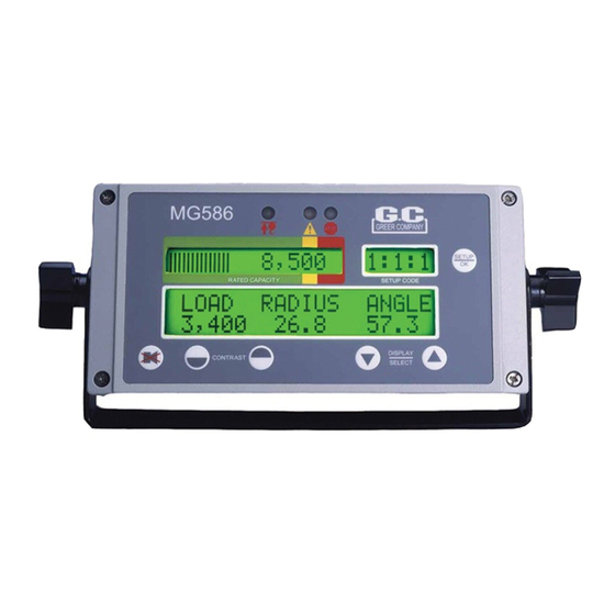
Page 8: Operator's Display Console - Overview
In addition, information regarding any warnings or alarms will be flashed in this display area. GREER Company Page 8 of 44 ® MicroGuard 586 Operation/Setup Manual... -
Page 9: Push Buttons
The display mode keys are used to switch to different display formats showing various combinations of boom angle, boom length, and radius. GREER Company Page 9 of 44 ® MicroGuard 586 Operation/Setup Manual 1918 East Glenwood Place... -
Page 10: System Operation
Check that the correct setup code is displayed before operating the crane. See the Configuration Selection section for code DISPLAY CONTRAST SELECT setup instructions. GREER Company Page 10 of 44 ® MicroGuard 586 Operation/Setup Manual 1918 East Glenwood Place W458200 REV C 10/29/02... -
Page 11: Adjusting Display Contrast
Use the contrast adjustment keys to make the RATED CAPACITY SETUP CODE display area lighter or darker, as desired. DISPLAY CONTRAST SELECT Contrast GREER Company Page 11 of 44 ® MicroGuard 586 Operation/Setup Manual 1918 East Glenwood Place W458200 REV C 10/29/02 Santa Ana CA 92705... -
Page 12: Configuration Selection
To change the configuration code, use the display select arrows to show the desired option. • Press the setup key to select and move on to the next stage. GREER Company Page 12 of 44 ® MicroGuard 586 Operation/Setup Manual... -
Page 13: Parts-Of-Line
1. Once the correct parts-of-line are entered, the system will exit the configuration mode and return to the normal working screen. GREER Company Page 13 of 44 ® MicroGuard 586 Operation/Setup Manual... -
Page 14: Normal Operation
Warning: The operator must select the correct crane configuration code number for each setup configuration change. Inaccurate or non-selection of the appropriate Code Number will result in incorrect calculations and readings of the actual load weight and Percent of Rated Capacity. Refer to Configuration Selection, page 12. GREER Company Page 14 of 44 ®... -
Page 15: Approaching Overload
• The message “WARNING! – PRE-ALARM” will flash in the information portion of the screen. GREER Company Page 15 of 44 ® MicroGuard 586 Operation/Setup Manual 1918 East Glenwood Place W458200 REV C 10/29/02... -
Page 16: Maximum Capacity And Overload
As the bar graph moves into the overload (red-bordered) zone, crane motions remain cut. The message, “WARNING! – OVERLOAD” will flash in the information portion of the screen. GREER Company Page 16 of 44 ® MicroGuard 586 Operation/Setup Manual 1918 East Glenwood Place... -
Page 17: Two-Block Warning
The message, DISPLAY CONTRAST SELECT “WARNING! TWO BLOCKING” will appear in the information area of the display. GREER Company Page 17 of 44 ® MicroGuard 586 Operation/Setup Manual 1918 East Glenwood Place W458200 REV C 10/29/02... -
Page 18: Alarm Override
The alarm override button should be used with caution. Automatic audible alarms warning against overload, two-block dangers, and hazardous tipping conditions are temporarily silenced when this option is activated. Motion cutout may also be discontinued. GREER Company Page 18 of 44 ®... -
Page 19: Other Displayed Warnings
In such areas, the system displays a warning message, a yellow pre-warning light. GREER Company Page 19 of 44 ®... -
Page 20: System Care
IF IN DOUBT, SELECT THE CODE NUMBER AGAIN FOLLOWING THE STEPS OUTLINED IN THE SECTION ON CRANE OPTIONS AND SETUP CODES. CHECK THE ABOVE OPERATIONS BEFORE EACH SHIFT OR CRANE OPERATION GREER Company Page 20 of 44 ® MicroGuard 586 Operation/Setup Manual... - Page 21 • Boom Angle Signal – is generated within the extension reel, and designed to measure the angle of the boom relative to the horizon. GREER Company Page 21 of 44 ® MicroGuard...
- Page 22 If this cable has been damaged in any way, it should be carefully tested and may need to be replaced to ensure accurate transmission of signals. CHECK THE ABOVE OPERATIONS BEFORE EACH SHIFT OR CRANE OPERATION GREER Company Page 22 of 44 ®...
- Page 23 • Ensure that all electrical cables and connectors are free from damage and correctly connected. See anti-two-block switch installation. CHECK THE ABOVE OPERATIONS BEFORE EACH SHIFT OR CRANE OPERATION GREER Company Page 23 of 44 ® MicroGuard 586 Operation/Setup Manual...
- Page 24 Lower the hook block by winching down. NOTE: This action should disable the audible and visual alarms on the operator’s display console and activate the boom motions. CHECK THE ABOVE OPERATIONS BEFORE EACH SHIFT OR CRANE OPERATION. GREER Company Page 24 of 44 ® MicroGuard...
- Page 25 A load reading on the MicroGuard ® 586 Operator’s Display Console that falls outside of a 10% range may indicate a sensor problem. Call your Service Representative. MINIMUM SIX MONTHLY CHECK GREER Company Page 25 of 44 ® MicroGuard 586 Operation/Setup Manual...
-
Page 26: Faults
Follow the Boom Angle Sensor Zero section (page 37) in this manual. c. Remove the extension reel cover and use the Extension Reel Voltage Checks section (page 29) in this manual to verify operation of the extension reel. GREER Company Page 26 of 44 ®... - Page 27 This message indicates a problem with the System chip fitted inside the computer. Remove the computer lid and replace the System chip. Note: Use only proper chip insertion and removal tools to perform this operation. Never use a screwdriver. GREER Company Page 27 of 44 ® MicroGuard...
- Page 28 Fault messages should be reported to the Service Representative along with any noticeable damage done during System installation or routine checks. Please refer to Routine Checks and Maintenance in this manual. GREER Company Page 28 of 44 ®...
-
Page 29: Extension Reel Voltage Checks
DEGREES. EXTENSION SENSOR IS SET TO 5% (1/20 ) OF SENSOR DRIVE VOLTAGE WITH BOOM FULLY RETRACTED. MEASURE ALL VOLTAGES WITH A DIGITAL VOLTMETER SET TO DC VOLTS RANGE. GREER Company Page 29 of 44 ® MicroGuard 586 Operation/Setup Manual... -
Page 30: Computer Internal Status Indicators
D3, D4 and D7 OFF but all other indicators ON Replace computer • D3 OFF but all other indicators ON Check extension reel signal cable and internal voltages within extension reel. GREER Company Page 30 of 44 ® MicroGuard 586 Operation/Setup Manual... -
Page 31: Communication Indicator
After a display console. few seconds, the COMM indicator starts to flash at a fast rate and never stops. GREER Company Page 31 of 44 ® MicroGuard 586 Operation/Setup Manual... -
Page 32: Troubleshooting
Check that all LEDs within the computer are lit and that the communications LED (D6) is flashing – If not replace system chip. • Check the display cable for damage. GREER Company Page 32 of 44 ® MicroGuard 586 Operation/Setup Manual... -
Page 33: System Setup
It is recommended that the crane be configured with no stowed or erected jib (bare boom) and reeved with a single part-of-line. Accessing the Extension Reel Sensors Remove the cover from the extension reel by loosening and removing the 12 screws around the perimeter of the cover. GREER Company Page 33 of 44 ® MicroGuard 586 Operation/Setup Manual... -
Page 34: Entering Setup Mode
SETUP CODE window, check that the System is in RATED CAPACITY the NORMAL-working mode (NOT the configuration mode) with no error codes. DISPLAY CONTRAST SELECT GREER Company Page 34 of 44 ® MicroGuard 586 Operation/Setup Manual 1918 East Glenwood Place W458200 REV C 10/29/02... -
Page 35: Extension Reel Cable Guides
4 feet from center point of extension reel. Center point of extension reel Main base section of boom GREER Company Page 35 of 44 ® MicroGuard 586 Operation/Setup Manual 1918 East Glenwood Place W458200 REV C 10/29/02... -
Page 36: Installing The Reel-Off Cable
3) Turn the Extension Reel counterclockwise for 5 complete rotations. Note: A temporary marker placed on the Extension Reel can facilitate the rotation count. Pre-Tension is complete. GREER Company Page 36 of 44 ® MicroGuard 586 Operation/Setup Manual 1918 East Glenwood Place... -
Page 37: Boom Angle Sensor Zero
0.0°, angle sensor adjustment is necessary. 0.2°. 6. When finished, press to continue to the next setup step. GREER Company Page 37 of 44 ® MicroGuard 586 Operation/Setup Manual 1918 East Glenwood Place W458200 REV C 10/29/02... -
Page 38: Boom Extension Sensor Zero
3. Mechanically adjust the extension sensor clutch until the display reads zero (0.0). To do this, disengage the main gear wheel connected to the extension sensor by pulling the sensor arm in the direction shown. GREER Company Page 38 of 44 ® MicroGuard 586 Operation/Setup Manual... -
Page 39: Boom Length Trim
DISPLAY CONTRAST SELECT To make the length match the specified maximum length of the crane, press OK. GREER Company Page 39 of 44 ® MicroGuard 586 Operation/Setup Manual 1918 East Glenwood Place W458200 REV C 10/29/02... -
Page 40: Jib Selection Setup (Interlock)
The displayed selection text differs for each model of crane; therefore, the displayed text may not exactly match the text in the images below. For clarification or for more details, please contact the Greer Company. 1. Go to the JIB SELECTION screen. - Page 41 SETUP RATED CAPACITY SETUP CODE DISPLAY SELECT CONTRAST GREER Company Page 41 of 44 ® MicroGuard 586 Operation/Setup Manual 1918 East Glenwood Place W458200 REV C 10/29/02 Santa Ana CA 92705...
-
Page 42: Completion
1. When Setup is complete, press the UP ARROW button to exit the Setup Mode. 2. Replace the boom extension reel cover, ensuring that all 12 screws are fitted and evenly tightened. GREER Company Page 42 of 44 ® MicroGuard... - Page 43 GREER Company Page 43 of 44 ® MicroGuard 586 Operation/Setup Manual 1918 East Glenwood Place W458200 REV C 10/29/02 Santa Ana CA 92705...
- Page 44 GREER Company Page 44 of 44 ® MicroGuard 586 Operation/Setup Manual 1918 East Glenwood Place W458200 REV C 10/29/02 Santa Ana CA 92705...
Need help?
Do you have a question about the MicroGuard 586 and is the answer not in the manual?
Questions and answers