GREER Company MicroGuard 586 Manual
Rated capacity indicator systems
Hide thumbs
Also See for MicroGuard 586:
- Operation/setup manual (44 pages) ,
- Operation manual (25 pages) ,
- Quick manual (2 pages)
Table of Contents
Advertisement
Advertisement
Table of Contents
Troubleshooting

Related Manuals for GREER Company MicroGuard 586


Summary of Contents for GREER Company MicroGuard 586
- Page 1 MicroGuard Retrofit ® Rated Capacity Indicator Systems Calibration Testing...
-
Page 3: Table Of Contents
Table of Contents Introduction ......................................1 Required Tools ....................................2 Number Conversion ................................2 Operator’s Display Console................................3 Warning/Alarm Indicators ..............................3 Display Windows ..................................3 Push Buttons ....................................4 System Operation ..................................... 5 System Self-Test ..................................5 Configuration Selection ................................6 Normal Operation .................................. - Page 4 08 Calibrate Fly ..................................38 09 Stowed Jibs ..................................40 10 Digital Input ..................................42 11 Angle Rate ..................................43 Appendix A - Troubleshooting ..............................A-1 System Fault Messages ..............................A-1 Computer Replacement ..............................A-3 Extension Reel Voltage Checks ............................. A-4 Appendix B - Computer Troubleshooting...........................
-
Page 5: Introduction
Introduction Congratulations on choosing the new MicroGuard 586 Retrofit Rated Capacity Indicator System. ® This manual describes the calibration process for the MicroGuard Retrofit Rated Capacity Indicator ® System (hereinafter referred to as “the system”) in an on-site environment and assumes that there is no prior knowledge of the geometry of the crane other than data provided by the manufacturer. -
Page 6: Required Tools
Required Tools • 1/4” nut driver or T15 Torx driver • Digital or bubble level calibrated and accurate to 0.1° at level • 100 foot measuring tape - fiber type graduated in tenths of feet 1.0′ 1.1′ 1.23′ 1 ft 1 ft 1′-0″... -
Page 7: Operator's Display Console
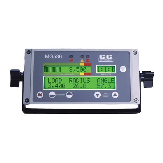
Operator’s Display Console Warning/Alarm Indicators Two-Block Pre-Warning Overload and Fault The red two-block lamp will illuminate when a two-block condition occurs (see “Two- Block Warning” on page 8). The yellow pre-warning lamp will illuminate at 90% of rated capacity (see “Approaching Overload”... -
Page 8: Push Buttons
Push Buttons Setup key enables the operator to setUP configure the system to match the actual setup of the crane. Codes are present for: • stowed jib attachments; if no stowed options are available, this code will not appear • crane configuration • number of parts-of-line key is AlARm OveRRiDe (cANcel) -
Page 9: System Operation
System Operation System Self-Test When the system is turned on, it goes through a brief self-testing process. All three alarm indicators will light up, all display windows will appear black, and the audible alarm will sound. The information display will then show the crane model and capacity chart number for the system configured. -
Page 10: Configuration Selection
Configuration Selection Configuration selection is required upon system power up; however, it can also be entered anytime by pressing the key. setUP Setup Code The first selection is fo the jib. Since no jibs are stowed, the system defaults to the main boom. Press the setUP/Ok key to continue. -
Page 11: Normal Operation
Normal Operation Percent of Rated Capacity Rated Capacity Actual Load Boom Angle Boom Length Percent of rated capacity indicates how near the operation is to full capacity and overload. The percent of rated capacity meter progresses to the right as the percentage increases. As long as the meter remains within the normal (green-bordered) zone, the percent of rated capacity is within normal operating limits. -
Page 12: Approaching Overload
Approaching Overload Pre-Warning Lamp The system continuously monitors the weight of the load suspended below the boom head. The system compares this information with rated capacity data stored within the computer. When the rated capacity of the configuration reaches 90%, the percent of rated capacity meter progresses from the normal (green-bordered) zone into the caution (yellow-bordered) zone. -
Page 13: Two-Block Warning
Two-Block Warning Two-Block Lamp If the hook block is on a collision course with the head machinery at the end of the boom, the two- block lamp will illuminate and an audible alarm will sound continuously. The message: “!WARNING! TWO BLOCKING” will appear in the information window. Crane motions (boom extend, boom down, and winch up) are cut in order to prevent damage to the crane and the endangerment of persons near the lifting area. -
Page 14: Adjusting The Contrast
Adjusting the Contrast Changes in temperature and lighting conditions may require adjustment of the display contrast. Use the keys to lighten or darken the display as required. cONtRAst Lighter Darker MG586 Calibration W458199 Rev C 06/07... -
Page 15: Preliminary Checks And Measurements
Preliminary Checks and measurements The following pages provide a list of measurements that must be recorded and double-checked for accuracy. If measurements exist in the system from a previous application, or if no measurements exist, they must be entered into the system. Any data supplied by the crane manufacturer in the crane application data sheet stored in the system must be validated before calibration begins. -
Page 16: Boom Pivot Dimensions
Boom Pivot Dimensions Boom Pivot Main Boom Boom Hoist Cylinder Upper Pivot Boom Hoist Cylinder Boom Hoist Cylinder Lower Pivot The boom should be in a horizontal position (0°) when taking the following measurements. Use the space provided in Appendix C to record the measurements: Dimension “L”... -
Page 17: Boom Hoist Cylinder Dimension
Boom hoist Cylinder Dimension Dimension “M” –This is the distance measured around the outside of the cylinder rod, divided by 12. uSe The SPACe PROvIDeD IN APPeNDIx C TO ReCORD The meASuRemeNTS. Rope Dimensions Rope Boom Pivot Dimension “W” – The distance between the center of the boom pivot and the winch rope perpendicular to the rope. -
Page 18: Stowed Jib Dimensions
Stowed Jib Dimensions Balanced Pick Point = Center of Gravity Main Boom Jib Assembly ImPORTANT! JIB meASuRemeNTS mAy Be TAkeN WITh The JIB STOWeD, hOWeveR JIB muST Be RemOveD PRIOR TO BOOm CAlIBRATION. uSe The SPACe PROvIDeD IN APPeNDIx C TO ReCORD The meASuRemeNTS. Installation Checks Check wiring and EPROM installations (on page B-4 for wiring schematic). -
Page 19: Installing The Reel-Off Cable
Installing the Reel-Off Cable ImPORTANT! The Reel-Off CABle muST Be PROPeRly PRe-TeNSIONeD. ThIS PROCeDuRe keePS The CABle TAuT AT All TImeS, WITh CONTROlleD, STeADy exIT fROm The exTeNSION Reel. Pre-Tension Steps Fully retract the boom. Slowly rotate the extension reel clockwise until a “click” is heard, indicating that the clutch inside the reel is engaged. -
Page 20: Adjusting The Extension Sensor
Adjusting the extension Sensor With the level on the boom reading 0°, rotate the extension sensor arm outward to disengage the gear. Extension Sensor Extension Sensor Gear Sensor Arm Rotate the sensor arm outward in this direction to disengage the gear. Rotate the extension sensor clockwise until the end of the pot is reached. -
Page 21: Entering Calibration Data
entering Calibration Data mWARNINg WheN The SySTem IS IN CAlIBRATION mODe, AuTOmATIC OveRlOAD CONTROlS ARe DISABleD. The CRANe OPeRATOR IS ReSPONSIBle fOR PROPeR lOADINg Of The CRANe WhIle PeRfORmINg CAlIBRATION. To enter calibration data it is necessary to put the system in calibration mode. To access calibration mode: Hold down the keys simultaneously for about six (6) seconds. - Page 22 The system is now in calibration mode and ready to receive calibration data. Press the UP ARROW key to scroll through the following menus: DOWN ARROW 00 Information – Displays system specific information. 01 Reset Data – Displays the status of the system personality. 02 Dimensions –...
-
Page 23: Information
00 Information This menu enables viewing of system specific information, error codes, and recommended diagnostic procedures. The Main Information screen shows you the display model and Crane Data Chart used. The Error Codes screen enables you to view system error codes (see System Fault Messages on page A-1 for description). - Page 24 The Crane Data screen shows the crane data chart number. This file is used for system RESET. From the Serial Number screen, press the key. UP ARROW The Diagnostics screens display a number of recommended procedures necessary to complete the calibration.
-
Page 25: Crane Data
01 Crane Data This menu will display the status of the system personality. If the system has been reset and is functioning correctly, the display will read “Personality is good.” If the system has been altered or is not functioning correctly, the display will read “Personality is bad.” In order for a new calibration to begin, the crane data must be reset. - Page 26 You will be prompted again to confirm the reset command be pressing “Y” ( DOWN ARROW key), or “N” ( key). UP ARROW You will be prompted one more time to confirm the reset command be pressing “Y” ( DOWN ARROW key), or “N”...
- Page 27 Press the UP ARROW key to go to the backup menu. To backup the crane data, press the setUP/Ok key. You will be prompted to confirm the reset command be pressing “Y” ( key), or “N” ( DOWN ARROW ARROW key).
- Page 28 The system also contains a retrieval function that allows the installer/calibrator to restore a copy of the personality information to the program chip in the event of an error. Press the key to go to the reset menu. UP ARROW To retrieve the crane data, press the key.
-
Page 29: Dimensions
02 Dimensions This menu is for entering the dimensions recorded in Appendix C. Press the setUP/Ok key to enter the routine. Press either the UP ARROW DOWN ARROW key to modify the displayed values. When the correct value is displayed, press the key to save and setUP/Ok continue. -
Page 30: Angle Sensor
03 Angle Sensor This routine is used to set the Zero and Span of the angle sensor. Press the key to enter the routine. setUP/Ok Position the boom at 0° and press the key. The angle sensor is now zeroed. DOWN ARROW Raise the boom to and angle of 65-70°... -
Page 31: Extension Sensor
04 extension Sensor This routine is used to set the Zero and Span of the extension sensor. Press the key to enter the routine. setUP/Ok Fully retract the boom and press the key. The extension sensor is now zeroed. DOWN ARROW Fully extend the boom and measure the length of the fully extended boom. -
Page 32: Pressure
05 Pressure This routine uses a calibration load to compute the diameter of the hoist cylinder, if the diameter is already known or is easily measured, simply skip the calibration option and enter the value directly at the end of this routine. ImPORTANT! ThIS DImeNSION IS CRITICAl AND ShOulD Be meASuReD TO WIThIN 1/10Th INCh. - Page 33 Enter the weight of the calibration load including all shackles and hook weights. The load should be as large a mass as is safe for the crane to pick with the boom as far retracted as possible at an angle of approximately 60°. If only small test loads are available, use a longer boom length and possibly a little lower boom angle to induce more pressure in the cylinder base.
- Page 34 Set down the calibration load, allow it to settle, and then confirm the weight. Press “OK” ( key) to continue. ARROW The computer will then calibrate the piston diameter. If the piston diameter was known prior to entering the routine, enter the value. Press either key to modify the displayed value and press the UP ARROW DOWN ARROW...
-
Page 35: Radius/Moment
06 Radius/moment This routine calibrates the natural moment and radius of the boom, taking into account its deflection under its own weight. mWARNINg mAke SuRe The CRANe IS SeT uP IN ACCORDANCe WITh The mANufACTuReR’S OPeRATION mANuAl fOR mAxImum STABIlITy. eNSuRe ThAT All BOOm exTeNSIONS AND lOADS lIfTeD ARe WIThIN The APPROPRIATe lOAD ChARTS AND lImITS. - Page 36 Press the setUP/Ok key to enter the routine. To start a new calibration, press “Y” ( key), otherwise press “N” ( key) to UP ARROW DOWN ARROW check an existing calibration. If no is selected, you will be prompted for a boom length to calibrate. You may re-calibrate any boom length, by extending to that length and calibrating.
- Page 37 Telescope to the desired length. Boom to a high or low angle. Always check the computer to ensure that the angle is identified as a ‘high” or “low” angle. If the display has indicated a different setting, use the UP ARROW key to change to “high”...
- Page 38 Confirm the calibration. Press “Y” ( UP ARROW key) to store the calibration point, otherwise press “N” ( key) to correct any errors. DOWN ARROW To restart a calibration length, press the key. cANcel Calibrated lengths are stored in personality memory. To re-enter a single length, restart the radius/ moment routine.
- Page 39 After saving this calibration point, the system will be showing the proper hook weight and working with the corrected radius. You can boom up to 45° and recheck the radius (45° is probably the worst case angle, so if the radius still checks good here you can move on to the next point with confidence).
-
Page 40: Deflection
07 Deflection This routine is used to quantify the amount that a boom or attachment bends, or deflects under load. The boom has its own bending factor called “F.” Each jib combination can have its own independent “F” value. Before entering the routine, the display will show the angle of the boom head under no load and under the current load. - Page 41 Press either the up arrow key or the down arrow key to edit the “F” number manually without entering a radius; this is useful to trim the BDC up or down a bit. Press either the UP ARROW key to modify the displayed value and press the key to enter the DOWN ARROW setUP/Ok...
-
Page 42: Calibrate Fly
08 Calibrate fly This routine is used to perform a calibration on each jib configuration. The “edit” option can be used to manually enter pre-calibrated data. This option assists in trimming an existing calibration. mWARNINg mAke SuRe The CRANe IS SeT uP IN ACCORDANCe WITh The mANufACTuReR’S OPeRATION mANuAl fOR mAxImum STABIlITy. - Page 43 Press the setUP/Ok key to edit the data for the selected fly. Press the key again to enter the data. If jib data is known, it is okay to enter it. If not setUP/Ok the system will calibrate the length, weight of jib, etc. Enter the weight of the fly (in tenths of pounds).
-
Page 44: Stowed Jibs
09 Stowed Jibs This routine is used to enter data for stowed attachments. ImPORTANT! ThIS INfORmATION ShOulD Be eNTeReD BefORe PeRfORmINg A mAIN BOOm RADIuS/ mOmeNT CAlIBRATION, If IT IS TO Be CAlIBRATeD WITh A STOWeD ATTAChmeNT. Press the setup/ok key to enter the routine. Press the key to edit the data for the selected jib. - Page 45 Press the UP ARROW key to select the next group of data to enter and press the setUP/Ok key. Enter the remaining data as described previously. When all the data has been entered, press the key to return to the main menu. cANcel Notes: Stowed G –...
-
Page 46: Digital Input
10 Digital Input This routine shows the status of digital inputs and outputs. Press the key to enter the routine. setUP/Ok Press the UP ARROW key or DOWN ARROW key to view the status of the inputs. MG586 Calibration W458199 Rev C 06/07... -
Page 47: Angle Rate
11 Angle Rate Often loads will change drastically when booming down. This routine compensates for this type of change. Two compensation speeds are allowed: ”Slow” rate compensation and ”Fast” rate compensation. The “Actual” rate of boom movement is also displayed in this routine. Press the key to enter the routine. -
Page 48: Appendix A - Troubleshooting
Appendix A - Troubleshooting System fault messages When the system detects a fault, the red warning lamp will illuminate and the message, “WARNING: SYSTEM FAULT” will flash on the display. When a more serious fault is detected, the message, “WARNING: SYSTEM OUT OF SERVICE” will flash. To determine the fault, press the UP ARROW or DOWN ARROW key once or twice. - Page 49 Fault Message Corrective Action Check ATB Wiring This message indicates an anti two-block wiring problem usually due to an electrical short to the boom or a damaged cable. Inspect/check cabling and connections from computer to extension reel on the side of the boom.
-
Page 50: Computer Replacement
Computer Replacement To remove the computer unit: Place the boom in its rest. Turn off electrical power. Disconnect all electrical connectors from/to the computer. Disconnect hydraulic hose connections from/to the computer. Remove computer from mounting. mWARNINg The hyDRAulIC hOSeS CONNeCT DIReCTly TO The BOOm hOIST CylINDeR. DO NOT OPeRATe The CRANe uNleSS The COmPuTeR hAS BeeN PROPeRly RePlACeD OR The hyDRAulIC CONNeCTIONS ARe PROPeRly CAPPeD. -
Page 51: Extension Reel Voltage Checks
extension Reel voltage Checks If problems occur with the two-block alarm operation, angle, or extension sensor, the following chart details voltage checks that may be made within the extension reel. Follow the action column before measuring voltages at the specified points in the voltmeter connection columns. Measure all voltages with a digital voltmeter set to DC volts range. -
Page 52: Appendix B - Computer Troubleshooting
Appendix B - Computer Troubleshooting Computer Internal Status Indicators The computer unit contains six LED indicators that provide an aid to checking presence of power supply voltages and communications between the computer and display console. There are five power indicators (D2 through D6) and one communications indicator (D7), all Indicators are bright green light emitting diodes. -
Page 53: Power Indicator States And Actions
Power Indicator States and Actions Power Indicator State Corrective Action All indicators OFF Check power and ensure that PTO switch is properly engaged. D2 ON but all other indicators OFF Check display console cable and connection. D5 OFF but all other indicators ON Replace computer D3, D4 and D7 OFF but all other indicators ON Replace computer... -
Page 54: Start-Up Problems
Start-up Problems Condition Corrective Action Display unit lights and alarms are flashing; the • Make sure the PTO is fully engaged. computer unit sounds as if it is buzzing. During system setup, it is not possible to adjust the • Make sure the extension reel is installed the angle sensor. -
Page 55: System Schematic
System Schematic (optional) BOOM EXTENSION REEL PORT 1 PISTON SIDE COMPUTER UNIT PORT 2 RODSIDE POWER CABLE #1 CABLE #4 & FKO SWING SWITCHES OR SWING POT (optional) DISPLAY UNIT MG586 Calibration W458199 Rev C 06/07... -
Page 56: Terminal Block Positions And Functions
Terminal Block Positions and functions CABLE 1 CABLE 2 CABLE 3 CABLE 4 POWER DISPLAY SWING EXTENSION & FKO REEL CABLE 1: Power and FKO Connections Color Function Connection Black System Ground JP3-1 (Battery -VE) System Power JP3-2 (Battery +VE) System Supply JP3-3 (Battery +VE) Jumper... -
Page 57: Suggested Swing Connections
CABLE 2: Display Connections Color Function Connection Not Used JP12-6 (DSPLY 1 GND) CABLE 3: Swing Connections Swing Switch Connections Color Function Connection Green Rear JP9-1 (DIN0) White Side JP9-2 (DIN1) Front JP9-3 (DIN2) Black Bet. Tires in-Line Front/Rear JP9-4 (DIN3) JP9-5 (SW PWR) JP10-1 (DIN4) JP10-2 (DIN5) - Page 58 Over Rear/Over Side Switch Over Rear DIN 0 Over Side DIN 1 In-Line DIN 3 + VP Over Rear/Side & In-Line/Houselock Over Rear DIN 0 Green Over Side DIN 1 White In-Line DIN 3 (Houseblock) Black + VP CABLE 4: Extension Reel Connections Color Function Connection...
- Page 59 MG586 Calibration W458199 Rev C 06/07...
-
Page 60: Appendix C - Measurement Record
Appendix C - measurement Record Use the space provided below to enter the necessary dimensions. Dimensions must be entered into the system in feet and tenths of a foot. Please make sure to convert any measurements if necessary before recording them. Callout Description Measurement... - Page 61 Callout Description Measurement Menu 05 - Pressure This is the distance measured around the outside of the cylinder rod, divided by 12 (see “Boom Hoist Cylinder Dimension” on page 13). Menu 07 - Deflection The deflected radius of the boom under calibrated load. Menu 08 - Calibrate Fly Weight Offset...
- Page 62 Callout Description Measurement Fly Hook Retracted, Low Angle Radius Retracted, High Angle Radius Extended, High Angle Radius Extended, Low Angle Radius Menu 09 - Stowed Jib Stowed G Stowed T Stowed Deduct Jib Weight MG586 Calibration W458199 Rev C 06/07...
- Page 63 Radius/moment Data (0,0) Boom Length (fully retracted) (fully extended) Load Verification Displayed Displayed Displayed Measured Radius Displayed Actual Load Test # Length Angle Radius Radius Error Load Load Error MG586 Calibration W458199 Rev C 06/07...
- Page 64 Load Verification Displayed Displayed Displayed Measured Radius Displayed Actual Load Test # Length Angle Radius Radius Error Load Load Error MG586 Calibration W458199 Rev C 06/07...
-
Page 65: Main Boom Testing Worksheet
main Boom Testing Worksheet Following each main boom calibration, perform a series of tests that will sufficiently show the accuracy of the calibration in all working areas of the main boom. Test each boom, two different loads at three different lengths and three different angles for each length of main boom. - Page 66 Displayed Displayed Displayed Measured Radius Displayed Actual Load Notes Length Angle Radius Radius Error Load Load Error MG586 Calibration W458199 Rev C 06/07...
-
Page 67: Attachment Testing Worksheet
Attachment Testing Worksheet Attachment and Offset _______________________________________________________________ Main Boom _______________________________________________________________ Test Number _______________________________________________________________ Test Displayed Displayed Displayed Measured Radius Displayed Actual Load Number Length Angle Radius Radius Error Load Load Error MG586 Calibration W458199 Rev C 06/07... - Page 68 Attachment and Offset _______________________________________________________________ Main Boom _______________________________________________________________ Test Number _______________________________________________________________ Test Displayed Displayed Displayed Measured Radius Displayed Actual Load Number Length Angle Radius Radius Error Load Load Error MG586 Calibration W458199 Rev C 06/07...
- Page 69 Attachment and Offset _______________________________________________________________ Main Boom _______________________________________________________________ Test Number _______________________________________________________________ Test Displayed Displayed Displayed Measured Radius Displayed Actual Load Number Length Angle Radius Radius Error Load Load Error MG586 Calibration C-10 W458199 Rev C 06/07...
- Page 70 Attachment and Offset _______________________________________________________________ Main Boom _______________________________________________________________ Test Number _______________________________________________________________ Test Displayed Displayed Displayed Measured Radius Displayed Actual Load Number Length Angle Radius Radius Error Load Load Error MG586 Calibration C-11 W458199 Rev C 06/07...
- Page 71 Attachment and Offset _______________________________________________________________ Main Boom _______________________________________________________________ Test Number _______________________________________________________________ Test Displayed Displayed Displayed Measured Radius Displayed Actual Load Number Length Angle Radius Radius Error Load Load Error MG586 Calibration C-12 W458199 Rev C 06/07...
-
Page 72: Fraction To Decimal Conversion Chart
fraction to Decimal Conversion Chart Fraction Decimal Fraction Decimal 1/64 .015625 33/64 .515625 1/32 .03125 17/32 .53125 3/64 .046875 35/64 .546875 1/16 .0625 9/16 .5625 5/64 .078125 37/64 .578125 3/32 .09375 19/32 .59375 7/64 .109375 39/64 .609375 .125 .625 9/64 .140625 41/64 .640625... - Page 73 MG586 Calibration C-14 W458199 Rev C 06/07...
- Page 75 Greer Company is a part of Tulsa Winch Group. www.team-twg.com As a leader in product innovation, Greer Company is committed to the ongoing improvement of its equipment. We reserve the right to make changes to our products without notice. W458199 Rev. C 06/07...
Need help?
Do you have a question about the MicroGuard 586 and is the answer not in the manual?
Questions and answers