GREER Company MICROGUARD 414 Troubleshooting Manual
Hide thumbs
Also See for MICROGUARD 414:
- Operator's manual (21 pages) ,
- Troubleshooting manual (84 pages)

Related Manuals for GREER Company MICROGUARD 414


Summary of Contents for GREER Company MICROGUARD 414
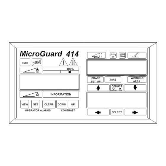
- Page 1 MICROGUARD ® TROUBLE SHOOTING MANUAL LATTICE CRANES MicroGuard 414 TEST 100% WORKING CRANE TARE AREA SET UP DEDUCT ERECTED TARE INFORMATION VIEW CLEAR DOWN OPERATOR ALARMS CONTRAST SELECT...
- Page 2 Duty ROM Replacement Page 17 Page 18 Glossary Page 21 Computer Layout Page 22 Termination Board Layout Boom Cable Connector Wiringvb Page 23 Page 23 Junction Box Wiring MicroGuard 414 Trouble Shooting Manual Page 2 of 23 March 2, 2006...
- Page 3 The lower visual alarms and can be configured to cause function right display gives information about the currently kick-out. selected crane configuration. The MicroGuard 414 indicator provides the operator with a continuous display of: • Rated Capacity •...
- Page 4 Group C Memory faults CODE • Group D General faults NO FAULTS NO DUTY FOUND CURRENT DUTY BAD CONFIGURATION UNCALIBRATED 2 HZ OSCILLATOR FAULT CODES GROUP “A” ANALOG SENSORS MicroGuard 414 Trouble Shooting Manual Page 4 of 23 March 2, 2006...
- Page 5 Sensor 2 Extension Sensor (Not Used) Whip Load transducer Sensor 3 Boom Angle Sensor 4 S’structure Angle (Not Used) Swing Pot’r “A” Sensor 5 Swing Pot’r “B” Sensor 6 MicroGuard 414 Trouble Shooting Manual Page 5 of 23 March 2, 2006...
- Page 6 Fault 96 Swing potentiometer “A” Swing potentiometer “B” This sequence continues up to the maximum fault code of 127 which is the sum of all group “A” fault codes. MicroGuard 414 Trouble Shooting Manual Page 6 of 23 March 2, 2006...
- Page 7 If the voltages are out of range it may be necessary to replace the computer. Before replacing the computer, refer to CRANE WARNING SYSTEMS INC. Product Support Department 863-619-5585 MicroGuard 414 Trouble Shooting Manual Page 7 of 23 March 2, 2006...
- Page 8 Computer Board will need to be replaced. If the voltage is within range, reconnect each cable, one at a time, checking the Analog Drive Voltage after each cable is connected. MicroGuard 414 Trouble Shooting Manual Page 8 of 23 March 2, 2006...
- Page 9 The display should have TX0 (main load transducer) displayed, if not, Press the Left Arrow (5) and then use the Up (3) or Down (4) Arrow keys to select TX 0. Press Select (1). MicroGuard 414 Trouble Shooting Manual Page 9 of 23 March 2, 2006...
- Page 10 Gently apply pressure on the cell. The bits should rise with pressure. GREEN, SIGNAL + PIN “D” 350Ω +/-10Ω WHITE, SIGNAL− PIN”B” 350Ω +/-10Ω RED, DRIVE + BLACK, DRIVE− PIN “A” PIN “C” MicroGuard 414 Trouble Shooting Manual Page 10 of 23 March 2, 2006...
- Page 11 If the above voltage checks are within range and no grounds or opens are found in the wires, replace the Boom Angle Sensor as described on page 16 of this manual. MicroGuard 414 Trouble Shooting Manual Page 11 of 23 March 2, 2006...
- Page 12 AIN 5 and AIN 6 are out of range the swing potentiometer will need to replaced. Voltage measured betw een 2 and 4 = 5.25 volts. Voltage measured betw een 1 and 3 = 4.125 volts. MicroGuard 414 Trouble Shooting Manual Page 12 of 23 March 2, 2006...
- Page 13 It contains the load chart data for the crane on which it is fitted and must be the exact type for the load chart on the machine. DIGITAL I/O & ANALOG I/O MicroGuard 414 Trouble Shooting Manual Page 13 of 23 March 2, 2006...
- Page 14 Two-Block warning. Connect a jumper wire from the 0 volt terminal to the ATBIN terminal. The Two-Block warning should no longer be displayed. If the Two-Block warning remains MicroGuard 414 Trouble Shooting Manual Page 14 of 23 March 2, 2006...
- Page 15 D OUT 1 HIGH 0.2 VOLT 5 VOLT D IN 13 HIGH 12 VOLT 0.2 VOLT The voltage levels are approximations and small variations are to be expected. MicroGuard 414 Trouble Shooting Manual Page 15 of 23 March 2, 2006...
- Page 16 Replace the Computer Box cover and secure COMPUTER BOX REPLACEMENT with the four screws. Disconnect all cable from the Computer Box. Remove the four screws securing the Computer Box. MicroGuard 414 Trouble Shooting Manual Page 16 of 23 March 2, 2006...
- Page 17 Access the Main Computer Board. (refer to page 8 of this manual). With the power off remove IC7, the Personality ROM Chip from its socket. (Refer to General Chip Removal and Installation this manual). MicroGuard 414 Trouble Shooting Manual Page 17 of 23 March 2, 2006...
- Page 18 Energy exerted, in this case by the suspended weight of an object. GEOMETRY A branch of mathematics that deals with the measurement and relationships of points, lines, angles, surfaces and solids. GRADUATED Marked with degrees of measurement. MicroGuard 414 Trouble Shooting Manual Page 18 of 23 March 2, 2006...
- Page 19 A measure of the capacity of a sensor to respond to physical stimulus. SENSOR A device that responds to a physical stimulus and transmits a resulting impulse. SHEAVE A grooved wheel or pulley. MicroGuard 414 Trouble Shooting Manual Page 19 of 23 March 2, 2006...
- Page 20 The amount that a body weighs or the poundage to be carried by a horse in a handicap race. WRITE PROTECTED An area of memory to which a microprocessor cannot write data. ZERO The point from which graduation of a scale begins. MicroGuard 414 Trouble Shooting Manual Page 20 of 23 March 2, 2006...
- Page 21 COMPUTER BOARD LAYOUT EXEC DUTY PERS LAYOUT OF MAIN COMPUTER BOARD IC2 EXECUTIVE ROM IC3 DUTY ROM IC7 PERSONALITY CHIP IC8 RAM CHIP (SOME MAY NOT BE REMOVABLE). MicroGuard 414 Trouble Shooting Manual Page 21 of 23 March 2, 2006...
- Page 22 DIN11 +5VB DIN12 AIN5 DIN13 BOARD TX1+ AIN6 DIN14 TX1- DIN15 ATBIN ATBOUT Cable 2 Cable 1 Cable 3 Cable4 Cable 5 Cable 6 Cable 7 Cable 8 MicroGuard 414 Trouble Shooting Manual Page 22 of 23 March 2, 2006...
- Page 23 MicroGuard 414 Trouble Shooting Manual Lattice Cranes MicroGuard 414 Trouble Shooting Manual Page 23 of 23 March 2, 2006...
Need help?
Do you have a question about the MICROGUARD 414 and is the answer not in the manual?
Questions and answers