Table of Contents
Advertisement
Quick Links
Advertisement
Table of Contents

Related Manuals for GREER Company MicroGuard 510 Retrofit


Summary of Contents for GREER Company MicroGuard 510 Retrofit
- Page 1 MicroGuard Retrofit ® Rated Capacity Indicator System Calibration...
-
Page 3: Table Of Contents
Contents Introduction ......................................1 Required Tools ....................................2 Number Conversion ................................2 ® The MicroGuard 510 Display ..............................3 Command Entry ..................................3 Number Entry ..................................... 3 Preliminary Checks and Measurements ..........................4 Boom Pivot Dimensions ................................. 4 Winch Dimensions ................................... 5 Boom Cylinder Dimensions .............................. - Page 4 Appendix A - Measurement Record ............................ A-1 Fraction to Decimal Conversion Chart ........................A-5 Appendix B - Computer Troubleshooting........................... B-1 Computer Internal Status Indicators ......................... B-1 Power Indicator States and Actions ..........................B-2 Communication Indicator ..............................B-2 Start-up Problems ................................B-3 System Schematic ................................
-
Page 5: Introduction
Introduction Congratulations on choosing the new MicroGuard 510 Retrofit Rated Capacity Indicator System. ® This manual describes the calibration process for the MicroGuard Retrofit Rated Capacity Indicator ® System (hereinafter referred to as “the system”) in an on-site environment and assumes that there is no prior knowledge of the geometry of the crane other than data provided by the manufacturer. -
Page 6: Required Tools
Required Tools • 1/4” nut driver or T15 Torx driver • Digital or bubble level calibrated and accurate to 0.1° at level • 100 foot measuring tape: fiber type graduated in tenths of feet 1.0′ 1.1′ 1.23′ Tape Measure graduated in tenths 1 ft of a foot Typical Tape Measure... -
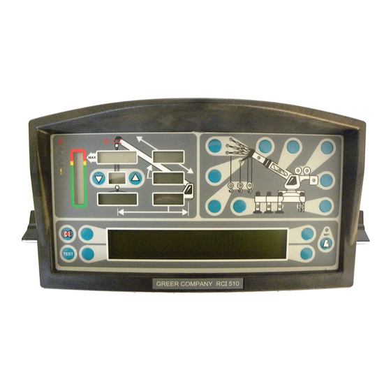
Page 7: The Microguard 510 Display
The MicroGuard ® 510 Display Command Entry The keys that are identified as A, B, C, and D will be used most for the procedures described in this document and their function will vary depending on the routine being performed. Commands for each routine will show in the information window as text adjacent to the keys. -
Page 8: Preliminary Checks And Measurements
Preliminary Checks and Measurements The following pages provide a list of measurements that must be recorded and double-checked for accuracy. If measurements exist in the system from a previous application, or if no measurements exist, they must be entered into the system. Any data supplied by the crane manufacturer in the crane application data sheet stored in the system must be validated before calibration begins. -
Page 9: Winch Dimensions
Winch Dimensions Centerline of Rotation Rear Winch Front Winch Swing Offset Sheave Radius Dimension “G0” and “G1” – The horizontal distance between the center of the front and rear winch (respectively) and the center of the boom pivot. Dimension “H0” and H1” – The vertical distance between the center of the front and rear winch (respectively) and the center of the boom pivot. -
Page 10: Boom Cylinder Dimensions
Boom Cylinder Dimensions Dimension “M” –This is the distance measured around the outside of the cylinder rod, divided by 12. UsE ThE sPaCE PRovIDED IN aPPENDIx a To RECoRD ThE MEasUREMENTs. span Dimensions mWaRNING sETTING sPaNs oN ThE CRaNE WIll REqUIRE fUll ExTENsIoN of ThE BooM. MakE sURE ThE CRaNE Is sET UP aCCoRDING To ThE MaNUfaCTURER’s oPERaTIoN MaNUal To ENsURE MaxIMUM sTaBIlITy. -
Page 11: Auxiliary Head Dimensions
auxiliary head Dimensions Centerline of Boom Offset Angle X.X° Auxiliary Head Main Boom UsE ThE sPaCE PRovIDED IN aPPENDIx a To RECoRD ThE MEasUREMENTs. stowed jib Dimensions Balanced Pick Point = Center of Gravity Main Boom Jib Assembly Dimension “G” - This is the distance between the center of the boom pivot and the center of gravity of the stowed jib. -
Page 12: Installation Checks
Installation Checks Check wiring and EPROM installations (see Installation Manual for wiring schematic). Check swing switches, if fitted. Use the digital monitor screen (located under Menu 13 – Digital Inputs) on the MG510 to ensure that the switches operate properly. Digital input information for the wiring is located on Pages 6 and 7 in the installation guide. -
Page 13: Entering Calibration Data
Entering Calibration Data mWaRNING WhEN ThE sysTEM Is IN CalIBRaTIoN MoDE, aUToMaTIC ovERloaD CoNTRols aRE DIsaBlED. ThE CRaNE oPERaToR Is REsPoNsIBlE foR PRoPER loaDING of ThE CRaNE WhIlE PERfoRMING CalIBRaTIoN. To enter calibration data it is necessary to put the system in calibration mode. Once in calibration mode, you will have five (5) seconds to enter the security key sequence. -
Page 14: Menu 00 - Error Codes
Menu 00 – Error Codes Menu Up 00 Error Codes View System Error Codes Information Menu Down Exit TEST This menu displays error code and system information. Press the key adjacent to either “Menu Up” or “Menu Down” until “00 Error Codes” appears in the information window at the right. -
Page 15: Menu 01 - Crane Data
Menu 01 – Crane Data This menu displays the status of the personality. TEST Press the key adjacent to either “Menu Up” or “Menu Down” until “01 Crane Data” appears in the information window at the right. Press the key adjacent to “01 Crane Data” to enter the routine. TEST If the system has been reset and is functioning correctly the display will read “Personality is Good”. - Page 16 The system also contains a backup function that allows the installer/calibrator to retain a copy of the personality information after the unit is calibrated. This system consists of the following components: System Program Chip Battery Backed RAM Personality Chip System Program Chip (ROM) Battery Backed RAM Personality Chip To back up the personality data, press the...
-
Page 17: Menu 02 - Dimensions
Menu 02 - Dimensions This menu is used to enter the physical dimensions of the crane that were previously recorded in Appendix A. TEST Press the key adjacent to either “Menu Up” or “Menu Down” until “02 Dimensions” appears in the information window at the right. -
Page 18: Menu 03 - Extension Sensor
Menu 03 - Extension sensor This menu allows for entering the zero point and span of the extension sensor that were previously recorded in Appendix A. TEST Press the key adjacent to either “Menu Up” or “Menu Down” until “03 Extension Sensor” appears in the information window at the right. -
Page 19: Menu 04 - Angle Sensor
Menu 04 - angle sensor This menu is used to enter the zero point and span for the angle sensor. This is done using the digital level. TEST Press the key adjacent to either “Menu Up” or “Menu Down” until “04 Angle Sensor” appears in the information window at the right. -
Page 20: Menu 05 - Swing Potentiometer (If Equipped)
Menu 05 - swing Potentiometer (if equipped) This menu is used to enter the zero point and the swing of the swing potentiometer (if equipped). TEST Press the key adjacent to either “Menu Up” or “Menu Down” until “05 Swing Potentiometer” appears in the information window at the right. -
Page 21: Menu 06 - Pressure
Menu 06 - Pressure This menu is used to determine the pressure of the boom hoist cylinder. A calibrated load is needed to calculate the diameter of the boom hoist cylinder. It is a good idea for this load to be approximately 80% of the single part load rating. - Page 22 The question, “Perform Piston Dimension Calibration?” Will appear on the screen. If “NO” is selected the system will ask for a manual entry of the piston diameter and then exit the calibration routine. If you do not know the piston diameter, press the key adjacent to “Yes” to calculate.
- Page 23 Pick up the calibration load again and check that the display shows the correct amount. Allow the load to adjust for a few seconds if necessary. TEST Remember that the load will actually show the boom moment plus the load, because the system has not yet been calibrated for boom moment.
-
Page 24: Menu 07 - Radius/Moment
Menu 07 - Radius/Moment This menu is used to calibrate the radius and moment of the boom. TEST Press the key adjacent to either “Menu Up” or “Menu Down” until “07 Radius/Moment” appears in the information window at the right. Press the key adjacent to “07 Radius/Moment”... - Page 25 If you are checking an existing calibration, select “No”. You will be prompted to extend the boom to the necessary length to calibrate, or recalibrate a different length configuration. If “Yes” is pressed, you will be asked to confirm your request. Press the key adjacent to “Yes”. TEST Note: A new calibration will erase any and all radius moment data previously entered.
- Page 26 When you have finished, press the key adjacent to “Yes” to store the data. TEST After saving this calibration point, the system will be showing the proper hook weight and working with the corrected radius. You can boom up to 45° and recheck the radius (45° is probably the worst case angle, so if the radius still checks good here you can move on to the next point with confidence).
-
Page 27: Menu 08 - Boom Deflection
Menu 08 - Boom Deflection This menu is used to enter the deflection of the main boom under the weight of a calibrated load. TEST Press the key adjacent to either “Menu Up” or “Menu Down” until “08 Boom Deflection” appears in the information window at the right. - Page 28 Fully extend the boom at an angle greater than 60°. Lift a suitable calibration load. The load should induce significant deflection in the boom. Begin the calibration by pressing the key adjacent to “Edit” . Measure the loaded main boom radius and enter the value. Use the keys adjacent to the numerical values at the bottom of the window to scroll left or right and highlight each number.
-
Page 29: Menu 09 - Compensation
Menu 09 - Compensation This menu is used to enter data to compensate for fluctuating loads. Loads can change dramatically when booming down because of fluctuating pressures in the base side of the boom hoist cylinder. The rod side pressure transducer constantly monitors these pressure changes on the base and rod side of the boom hoist cylinder and sends its signals to the computer for processing. -
Page 30: Menu 10 - Erected Attachments
Menu 10 - Erected attachments This menu is used to calibrate attachment radii, moments, and dimensions. For systems without pre- calibrated flys, perform a calibration routine on each jib configuration. Select proper fly/jib configuration Before starting this procedure you must configure the jib or attachment while in normal operation mode. - Page 31 Set the boom to the fully extended and fully retracted high low angle positions. The system should display the correct configuration (i.e. fully extended at low angle; indicating it is gathering data with a fully extended boom at a low angle). If the reading is incorrect, press the key adjacent to the appropriate menu to correct the configuration.
-
Page 32: Menu 11 - Auxiliary Head
Menu 11 - auxiliary head This menu is for entering the dimensions of the auxiliary head. TEST Press the key adjacent to either “Menu Up” or “Menu Down” until “11 Auxiliary Head” appears in the information window at the right. Press the key adjacent to “11 Auxiliary Head”... -
Page 33: Menu 12 - Stowed Attachments
Menu 12 - stowed attachments This menu is used to enter data for stowed attachments. TEST Press the key adjacent to either “Menu Up” or “Menu Down” until “12 Stowed Attachments” appears in the information window at the right. Press the key adjacent to “12 Stowed Attachments” to enter the routine. Press the key adjacent to “Edit”. -
Page 34: Menu 13 - Digital Inputs
Menu 13 - Digital Inputs This menu is used to view the status of the digital inputs. For inputs from swing switches, see page TEST Press the key adjacent to either “Menu Up” or “Menu Down” until “13 Digital Inputs” appears in the information window at the right. -
Page 35: Menu 14 - Enable Attachments
Menu 14 - Enable attachments This menu is used to enable or disable available attachments in the system. TEST Press the key adjacent to either “Menu Up” or “Menu Down” until “14 Enable Attachments” appears in the information window at the right. Press the key adjacent to “14 Enable Attachments”... -
Page 36: Menu 15 - Enable Winches
Menu 15 - Enable Winches This menu is used to enable or disable the available winches in the system. TEST Press the key adjacent to either “Menu Up” or “Menu Down” until “15 Enable Winches” appears in the information window at the right. Press the key adjacent to “15 Enable Winches”... -
Page 37: Menu 16 - Data Retrieval
Menu 16 - Data Retrieval This menu is used to view radius/Moment, attachment data, and pressure data. IMPoRTaNT! DaTa CaN BE EDITED WhIlE IN ThIs RoUTINE. UsE CaUTIoN WhEN vIEWING ThIs INfoRMaTIoN so as NoT To EDIT aNy DaTa. TEST Press the key adjacent to either “Menu Up”... - Page 38 When you have finished, the system will display the previous menu. To edit the data further press the key adjacent to “Edit” and continue as previously described. To go to the next menu, press the key adjacent to “Exit”. The system will ask “Do you want to edit Fly data?”. Select the key adjacent to “Yes”. TEST The current fly is displayed.
-
Page 39: Menu 17 - Language
Menu 17 - language This menu is used to enter a different language for display (where appropriate and subject to availability). TEST Press the key adjacent to either “Menu Up” or “Menu Down” until “17 Language” appears in the information window at the right. Press the key adjacent to “17 Language”... - Page 40 MG510R Calibration W450256 Rev A 06/07...
-
Page 41: Appendix A - Measurement Record
appendix a - Measurement Record Use the space provided below to enter the necessary dimensions. Dimensions must be entered into the system in feet and tenths of a foot. Please make sure to convert any measurements if necessary before recording them. Callout Description Measurement... - Page 42 Callout Description Measurement Boom hoist Cylinder Dimensions (see page 6) This is the distance measured around the outside of the cylinder rod, divided by 12. Number of cylinders. span Dimensions (see page 6) This is the dimension between the center of the boom pivot and the center of the sheave with the boom fully extended.
- Page 43 Radius/Moment Data (0,0) (see page 20) Boom Length (fully retracted) (fully extended) Load Verification Displayed Displayed Displayed Measured Radius Displayed Actual Load Test # Length Angle Radius Radius Error Load Load Error MG510R Calibration W450256 Rev A 06/07...
- Page 44 Load Verification Displayed Displayed Displayed Measured Radius Displayed Actual Load Test # Length Angle Radius Radius Error Load Load Error MG510R Calibration W450256 Rev A 06/07...
-
Page 45: Fraction To Decimal Conversion Chart
fraction to Decimal Conversion Chart Fraction Decimal Fraction Decimal 1/64 .015625 33/64 .515625 1/32 .03125 17/32 .53125 3/64 .046875 35/64 .546875 1/16 .0625 9/16 .5625 5/64 .078125 37/64 .578125 3/32 .09375 19/32 .59375 7/64 .109375 39/64 .609375 .125 .625 9/64 .140625 41/64 .640625... - Page 46 MG510R Calibration W450256 Rev A 06/07...
-
Page 47: Appendix B - Computer Troubleshooting
appendix B - Computer Troubleshooting Computer Internal status Indicators The computer unit contains six LED indicators that provide an aid to checking presence of power supply voltages and communications between the computer and display console. There are five power indicators (D2 through D6) and one communications indicator (D7), all Indicators are bright green light emitting diodes. -
Page 48: Power Indicator States And Actions
Power Indicator states and actions Power Indicator State Corrective Action All indicators OFF Check power and ensure that PTO switch is properly engaged. D2 ON but all other indicators OFF Check display console cable and connection. D5 OFF but all other indicators ON Replace computer D3, D4 and D7 OFF but all other indicators ON Replace computer... -
Page 49: Start-Up Problems
start-up Problems Condition Corrective Action Display unit lights and alarms are flashing; the • Make sure the PTO is fully engaged. computer unit sounds as if it is buzzing. During system setup, it is not possible to adjust the • Make sure the extension reel is installed the angle sensor. -
Page 50: System Schematic
system schematic (optional) BOOM EXTENSION REEL PORT 1 PISTON SIDE COMPUTER UNIT PORT 2 RODSIDE POWER CABLE #1 CABLE #4 & FKO SWING SWITCHES OR SWING POT (optional) DISPLAY UNIT MG510R Calibration W450256 Rev A 06/07... -
Page 51: Terminal Block Positions And Functions
Terminal Block Positions and functions CABLE 1 CABLE 2 CABLE 3 CABLE 4 POWER DISPLAY SWING EXTENSION & FKO REEL CABLE 1: Power and FKO Connections Color Function Connection Black System Ground JP3-1 (Battery -VE) System Power JP3-2 (Battery +VE) System Supply JP3-3 (Battery +VE) Jumper... -
Page 52: Suggested Swing Connection
CABLE 3: Swing Connections Swing Switch Connections Color Function Connection Green Rear JP9-1 (DIN0) White Side JP9-2 (DIN1) Front JP9-3 (DIN2) Black Bet. Tires in-Line Front/Rear JP9-4 (DIN3) JP9-5 (SW PWR) JP10-1 (DIN4) JP10-2 (DIN5) JP10-3 (SW PWR) Swing Pot Connections JP11-1 (Positive Drive) JP11-2 (Negative Drive) JP11-3 (Swing Signal “A”) - Page 53 Over Rear/Over Side Switch Over Rear DIN 0 Over Side DIN 1 In-Line DIN 3 + VP Over Rear/Side & In-Line/Houselock Over Rear DIN 0 Green Over Side DIN 1 White In-Line DIN 3 (Houseblock) Black + VP CABLE 4: Extension Reel Connections Color Function Connection...
- Page 54 MG510R Calibration W450256 Rev A 06/07...
- Page 56 Greer Company is a part of Tulsa Winch Group. www.team-twg.com As a leader in product innovation, Greer Company is committed to the ongoing improvement of its equipment. We reserve the right to make changes to our products without notice. W450256 Rev. A 06/07...
Need help?
Do you have a question about the MicroGuard 510 Retrofit and is the answer not in the manual?
Questions and answers