GREER Company MICROGUARD 424 Calibration Procedure
Hide thumbs
Also See for MICROGUARD 424:
- Calibration manual (44 pages) ,
- Operation/troubleshooting operation/troubleshooting manual (52 pages) ,
- Installation manual (35 pages)
Table of Contents
Advertisement
Quick Links
GREER COMPANY
MicroGuard
TEST
5.82
3.46 ATB ALARM
VIEW
OPERATOR ALARMS
1918 EAST GLENWOOD PLACE SANTA ANA, CALIFORNIA 92705
714)259-9702 Phone
714)259-7626 Fax
MICROGUARD
CALIBRATION PROCEDURE
FOR MODELS USING
M414371A & M414380C PROGRAMS
424
100%
W
MAX
60%
W
INFORMATION
SET
CLEAR
DOWN
CONTRAST
424
Generic
57.2 8 F 49.1
O/R FULEXT 360
CRANE
SET UP
Lifting point
MAIN BOOM
UP
STOWED
WORKING
DEDUCT
AREA
DEDUCT
ERECTED
STOWED
SELECT
o
Advertisement
Table of Contents

Related Manuals for GREER Company MICROGUARD 424


Summary of Contents for GREER Company MICROGUARD 424
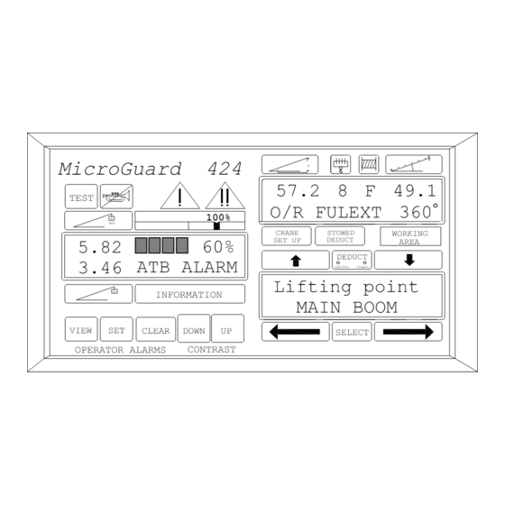
- Page 1 GREER COMPANY MICROGUARD CALIBRATION PROCEDURE FOR MODELS USING M414371A & M414380C PROGRAMS Generic MicroGuard 57.2 8 F 49.1 TEST O/R FULEXT 360 100% CRANE STOWED WORKING SET UP DEDUCT AREA 5.82 DEDUCT 3.46 ATB ALARM ERECTED...
-
Page 2: Table Of Contents
CONTENTS ♦ GENERAL INFORMATION PAGE 3 ♦ CALIBRATION PROCEDURES PAGE 4 ♦ COMMAND 00 PAGE 5 ♦ COMMAND 01 PERSONALITY PAGE 5 ♦ COMMAND 02 TEST/FAULT PAGE 7 ♦ FAULT CODES PAGE 8 ♦ NUMBER ENTRY PAGE 9 ♦ COMMAND 03 ZERO PAGE 11 ZERO PRESSURE TRANSDUCERS... -
Page 3: General Information
GENERAL INFORMATION After satisfactory installation of the complete system, ensure that it is correctly wired in accordance with the Wiring Diagram which is issued with the duty chip. Before carrying out any crane operations ensure that the machine is on firm and level ground and that the outrigger beams are fully extended and jacks are correctly extended to level the carrier. -
Page 4: Calibration Procedures
CALIBRATION PROCEDURES The Display Unit provides the interface between the user and the calibration program. The user communicates with the program interactively using a keypad. The displays provide information and data to enable the calibration to be carried out using only on screen prompts. Data entry is achieved by the use of six of the keypads on the standard display. -
Page 5: Command 00 Run
COMMAND 00 RUN Following correct entry of the calibration code then the system will be in the MONITOR mode and will be at Command 00 Run. Execution of this command will cause the system to carry out a system TEST and return to the working screen. - Page 6 WARNING If the system has been previously calibrated and the intention is only to access data or change only a portion of the previous calibration then DO NOT perform the initialization process which follows otherwise the entire previous calibration data will be lost. ENTRY TO CALIBRATION ROUTINES START THE ROUTINE BY PRESSING AND SELECT...
-
Page 7: Command 02 Test/Fault
COMMAND 01/0 SAVE On completion of a calibration it is necessary to carry out Command 01/0 SAVE and this is referred to at the end of this manual. There is no reason, however, why this command should not be used at any time during the intermediate stages of a calibration, for example at the end of a period of work or if desired after each section of a calibration has been completed. -
Page 8: Fault Codes
FAULT CODES GROUP "A" ANALOG SENSORS CODE NO FAULTS SENSOR 0 PISTON PRESSURE TRANSDUCER SENSOR 1 ROD SIDE PRESSURE TRANSDUCER SENSOR 2 EXTENSION SENSOR SENSOR 3 BOOM ANGLE SENSOR SENSOR 4 UPPERSTRUCTURE ANGLE SENSOR SENSOR 5 SWING POTENTIOMETER "A" SENSOR 6 SWING POTENTIOMETER "B"... -
Page 9: Number Entry
NUMBER ENTRY The MicroGuard system does not have number entry keys. A special number entry procedure is used to allow the simple entry of numbers. When numerical entry of data is required the center display will change to allow the entry of numbers. - Page 10 IN THE EXAMPLE WHICH FOLLOWS AN ARBITRARY NUMBER OF MINUS 123.45 HAS BEEN CHOSEN TO ILLUSTRATE THE USE OF THE PROCEDURE. ! ! ! ! " " " " SELECT THE FIRST DIGIT BY PRESSING SELECT WHEN AT PRESS ! ! ! ! "...
-
Page 11: Command 03 Zero
COMMAND 03 ZERO The Zero Command permits the calibration of the zero of most analog sensors. There are four sensors which can be zeroed by the use of command 03. Each sensor is allocated a number which corresponds to the input to which it is connected in the system. - Page 12 ! ! ! ! " " " " SCROLL TO 03 ZERO BY PRESSING START THE COMMAND BY PRESSING SELECT ! ! ! ! " " " " SCROLL TO Tx.0 BY PRESSING CONFIRM SELECTION OF THE SENSOR SELECT BY PRESSING THE DISPLAY WILL READ Tx.0 = XXX (actual input) START THE CALIBRATION OF Tx.0 BY PRESSING...
-
Page 13: Zero Extension Sensor
ZERO EXTENSION SENSOR The Extension Sensor is fitted with 130 ft. of shielded 2-wire cable. The cable cannot be shortened to accommodate varying boom lengths and the following method of pre-tensioning is recommended. ♦ Fully retract all the boom sections. ♦... -
Page 14: Zero Angle Sensor
ZERO BOOM ANGLE SENSOR NOTE THE INCLINOMETER OR MEASURING DEVICE USED TO CALIBRATE THE ANGLE OF THE MAIN BOOM MUST HAVE AN ACCURACY OF +/- 0.25°. USE OF A LESS ACCURATE DEVICE MAY RESULT IN CALIBRATION ERRORS. USE GREAT CARE IN THE CALIBRATION OF THE BOOM ANGLE SENSOR. ALL SUBSEQUENT CALCULATIONS ARE DEPENDENT ON THE ACCURACY OF THE CALIBRATION OF THIS SENSOR. -
Page 15: Command 04 Span
COMMAND 04 SPAN BOOM ANGLE SENSOR NOTE THE INCLINOMETER OR MEASURING DEVICE USED TO CALIBRATE THE ANGLE OF THE MAIN BOOM MUST HAVE AN ACCURACY OF +/- 0.25°. USE OF A LESS ACCURATE DEVICE MAY RESULT IN CALIBRATION ERRORS. USE GREAT CARE IN THE CALIBRATION OF THE BOOM ANGLE SENSOR. ALL SUBSEQUENT CALCULATIONS ARE DEPENDENT ON THE ACCURACY OF THE CALIBRATION OF THIS SENSOR. -
Page 16: Extension Sensor
EXTENSION SENSOR THROUGHOUT THIS PROCEDURE DO NOT FULLY EXTEND THE BOOM IF THIS WOULD CAUSE A TIPPING CONDITION. CARRY OUT CALIBRATION PROCEDURES ONLY WITHIN THE STABILITY LIMITS OF THE MACHINE. With the boom horizontal and fully retracted, measure the distance from the boom pivot to the hook center line. -
Page 17: Command 05 Swing
COMMAND 05 SWING THIS ROUTINE WILL ONLY BE EXECUTED ON MODELS THAT HAVE SWING POTENTIOMETERS. IF EQUIPPED WITH SWING SWITCHES CONTINUE WITH COMMAND 06 PRESSURE. Do not calibrate swing if you do not have swing potentiometers SCALE The swing command does not require the entry of measured data. All measurements of swing data are acquired automatically by the system during the calibration of the swing sensor. - Page 18 COMMAND 05 SWING (continued) POSITION THE CRANE UPPER DIRECTLY IN LINE OVER THE FRONT OF THE MACHINE START THE SLEW ZERO CALIBRATION SELECT BY PRESSING SELECT CONFIRM THE CALIBRATION (or abort with THE DISPLAY WILL READ 1 = ZERO ! ! ! ! SCROLL TO 2 DIRECTION BY PRESSING THE TOP DISPLAY WILL READ 2 = DIRECTION...
-
Page 19: Configuration Selection
CONFIGURATION SELECTION In the normal operational mode the system is programmed to remember the configuration last selected. Each time the system is powered up it will automatically choose that configuration. Only when the crane is rigged differently must a new configuration be selected. CRANE SET UP The menu for the crane set up consists of 6 to 8 consecutive steps depending on the options available. - Page 20 CONFIGURATION SELECTION START THE SELECTION OF CRANE CONFIGURATION BY PRESSING "CRANE SET UP" CRANE SET UP THIS CHART IS ONLY AN EXAMPLE! SCROLL TO CARRIER ! ! ! ! " " " " OUTRIGGERS OUTRIGGERS OUTRIGGERS ON TIRES PICK AND RIGGING FULLY EXT.
-
Page 21: Command 06 Pressure
COMMAND 06 PRESSURE ♦ USE "CRANE SET UP" TO SELECT FULLY EXTENDED OUTRIGGERS, MAIN BOOM, AND ATTACHMENTS IF EQUIPPED. ♦ DETERMINE THE WEIGHT OF THE CALIBRATION LOAD. THE CALIBRATION LOAD INCLUDES THE WEIGHT OF THE PINS AND SLINGS BUT DOES NOT INCLUDE THE WEIGHT OF THE BLOCK OR BALL. FOR BEST ACCURACY USE A LOAD WHICH EXCEEDS 50% OF THE MACHINE CAPACITY. -
Page 22: Command 07
COMMAND 07 MAIN BOOM (MODE A) RADIUS/MOMENT ♦ This command is used to calibrate the radius AND moment of the main boom. It requires data at high and low angles retracted and high and low angles with the boom extended to different lengths. ♦... - Page 23 Raise the retracted boom to an angle between 60° and 65° and measure the new radius. RAISE THE HOOK BLOCK. THEN STORE THE SELECT HIGH ANGLE DATA BY PRESSING USE THE NUMBER ENTRY ROUTINE TO ENTER THE NEW RADIUS THE DISPLAY WILL READ (" " " " ! ! ! ! ) START THE MOMENT CALIBRATION AT THE SELECT CURRENT LENGTH BY PRESSING...
- Page 24 THIRD LENGTH Maintain the same low angle, fully extend the main boom and measure the new radius RAISE THE HOOK BLOCK. THEN STORE THE LOW SELECT ANGLE DATA BY PRESSING USE THE NUMBER ENTRY ROUTINE TO ENTER THE NEW RADIUS THE DISPLAY WILL READ ("...
-
Page 25: Command 07
COMMAND 07 MAIN BOOM + MANUAL (MODE B) RADIUS/MOMENT ♦ This command is used to calibrate the radius AND moment of the main boom + manual or mode B. It requires data at high and low angles retracted and high and low angles with the boom extended to the different lengths. - Page 26 Raise the retracted boom to an angle between 60° and 65° and measure the new radius. RAISE THE HOOK BLOCK. THEN STORE THE SELECT HIGH ANGLE DATA BY PRESSING USE THE NUMBER ENTRY ROUTINE TO ENTER THE NEW RADIUS THE DISPLAY WILL READ (" " " " ! ! ! ! ) START THE MOMENT CALIBRATION AT THE SELECT CURRENT LENGTH BY PRESSING...
- Page 27 Raise the boom to an angle between 60° and 65° and measure the new radius. RAISE THE HOOK BLOCK. THEN STORE THE SELECT HIGH ANGLE DATA BY PRESSING USE THE NUMBER ENTRY ROUTINE TO ENTER THE NEW RADIUS THE DISPLAY WILL READ (" " " " ! ! ! ! ) START THE MOMENT CALIBRATION AT THE SELECT CURRENT LENGTH BY PRESSING...
-
Page 28: Command 08
COMMAND 08 BOOM DEFLECTION CORRECTION ♦ With the boom fully extended at an angle of approximately 65°, pick up the maximum permitted load. Check the load chart prior to making the lift. DO NOT EXCEED THE LOAD CHART. NOTE: It is permissible to use a known load less then the chart load for an angle of 65°, but use of the smaller load may reduce accuracy. -
Page 29: Command 09 Annular Gain
COMMAND 09 ANNULAR GAIN ♦ There are two pressure transducers fitted in the system. One measures the piston side pressure and the other measures the rod side pressure. Because these are not identical cross-sectional areas, data must be entered which defines the ratio of the two areas. This is referred to as annular gain (A.G.). This is calculated from the rod (R) and bore (B) diameters as follows: A.G. -
Page 30: Command 12 Winches
COMMAND 12 WINCHES Permits the "hiding" of a winch when it is not sold with the machine thereby removing unnecessary steps from the Operator Menu. This command operates by making a winch selectable or hidden by use of the following sequence: ! ! ! ! "... -
Page 31: Command 15 Alarm Limits
COMMAND 15 ALARM LIMITS In this routine the computer has provisions to put limits on various functions depending on which model of machine is being calibrated. The following explains each alarm/limit available: Free Bm Mode - This allows the operator to select the Main Boom + Manual configuration after the Manual section is already extended (if equipped). - Page 32 THE DISPLAY WILL READ Low Angle Alarm? y/n " $=Exit START THE CALIBRATION OF THE LOW ANGLE =Yes ALARM BY PRESSING $=Exit AFTER THE MESSAGE "CALIBRATING" THE DISPLAY WILL READ % SWL 0 = 100.000 START THE CALIBRATION OF % SWL #0 SELECT BY PRESSING SELECT...
- Page 33 $ $ $ $ SCROLL TO AREA ALARM BY PRESSING THE DISPLAY WILL READ Area Alarm? y/n $ $ $ $ SCROLL TO LOW ANGLE ALARM BY PRESSING THE DISPLAY WILL READ Low Angle Alarm? y/n $ $ $ $ SCROLL TO % SWL #0 BY PRESSING THE DISPLAY WILL READ % SWL 0 = 100.000...
-
Page 34: Command 16 Rope Data
COMMAND 16 ROPE DATA ♦ Maximum hoist rope tension is specified by the crane manufacturer for the size and type of wire rope used on the machine. This value is set at the initialization of the system. ♦ The Rope Data command permits the modification of the values and they should be entered in units of 1000 #. Example 11,700 # is entered as 11.70 Change data by use of the following sequence: ! ! ! ! -
Page 35: Command 17 Amplifier Gain
COMMAND 17 AMPLIFIER GAIN At the time of initialization the amplifier gain is set to the preferred value of 2. This value is suitable for the standard load cells and pressure transducers supplied with systems. For special application this gain setting may be modified as necessary. - Page 36 COMMAND 01/0 SAVE On completion of a calibration it is necessary to carry out Command 01/0 SAVE. The use of this command will ensure that a copy of the calibration, will be contained in the back-up memory. ! ! ! ! "...
- Page 37 SWITCH OFF POWER TO THE SYSTEM BEFORE REMOVING OR INSERTING INTEGRATED CIRCUITS A COPY OF THE CONTENTS OF THE "A" PORTION OF THE PERSONALITY IS NOW STORED TEMPORARILY IN MEMORY IN THE COMPUTER. THE CHIP IN SOCKET IC7 IS REMOVED AND WILL BE THE SERVICE BACK-UP CHIP.
-
Page 38: Command 19 Digital Inputs
COMMAND 19 DIGITAL INPUTS The logic status of digital inputs is displayed by use of this command. The inputs can be high or low. Low is indicated by 0 and high is indicated by 1. ! ! ! ! " " " " SCROLL TO 19 DIGITAL INPUTS BY PRESSING START THE COMMAND BY PRESSING... -
Page 39: Glossary
GLOSSARY OF TERMS ABORT The premature termination of a data entry procedure. ALARM A signal that warns or alerts such as a flashing light or loud noise. AMPLIFIER A device which takes an input and produces an output of greater magnitude (as in the case of a pressure transducer where a signal in the millivolt range is amplified to the level of up to ten volts). - Page 40 FORCE Energy exerted, in this case by the suspended weight of an object. GEOMETRY A branch of mathematics that deals with the measurement and relationships of points, lines, angles, surfaces and solids. GRADUATED Marked with degrees of measurement. HEIGHT The vertical distance from the ground to the tip of the boom or attachment.
- Page 41 SLEW OFFSET The horizontal distance from the boom pivot to the center of rotation SPAN An extent or spread between two limits. SPAN The calibration of an analog sensor between zero and maximum span. STOWED ATTACHMENT An attachment usually stowed on the main boom when not in use.
Need help?
Do you have a question about the MICROGUARD 424 and is the answer not in the manual?
Questions and answers