Advertisement
Q U I C K I N S T A L L G U I D E
Install the Enphase IQ Battery System
To install the Enphase IQ Battery 3T system or IQ Battery 10T system and the Enphase wall-mount bracket, read and follow all warnings and instructions in
this guide. Safety warnings are listed on the back of this guide. These instructions are not meant to be a complete explanation of how to design and install an
energy storage system. All installations must comply with national and local electrical codes and standards. Only qualified electricians shall install, trouble-
shoot, or replace the IQ Battery 3T or IQ Battery 10T.
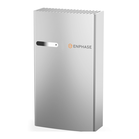
The IQ Battery system includes the Enphase IQ Battery(ies) with integrated Enphase IQ™ Microinverters. The Enphase IQ Gateway measures PV produc-
tion and home energy consumption. The IQ Battery system senses when it is optimal to charge or discharge the battery so that energy is stored when it is
abundant and used when scarce. IQ Battery systems are capable of providing backup power when an Enphase IQ System Controller is installed at the site.
Five unique installation
scenarios are shown:
Whole home backup with IQ System
Controller as service entrance and
PV combiner connected to IQ System
Controller. This is the preferred
configuration for back up of the entire main
load panel. This configuration supports up
to an 80A breaker for the PV circuit and an
80A breaker for battery storage.
NOTE:
1. For M215/M250 connection to Enphase
Energy System, refer tech brief at
https://
enphase.com/en-us/storage-m-series
2. M series microinverters require Gateway-S
metered.
Whole home backup with IQ System
Controller as service entrance and PV
combiner connected to main load panel.
This is the preferred configuration when you
back up the entire main load panel, and the
size of the PV combiner circuit is more than
80A. In this configuration, the PV combiner
circuit connection space in IQ System
Controller is left vacant. When existing PV
combiner circuits are connected to the main
load panel, and you want to add battery
storage to the system, you can keep the PV
combiner connected to the main load panel
and connect only the battery storage to IQ
System Controller.
Partial home backup with main load panel
as service entrance and PV combiner
connected to IQ System Controller. When
PV circuits breaker size is less than 80A,
this is the preferred configuration for partial
home backup with subpanel.
(Models Encharge-3T-1P-NA and Encharge-10T-1P-NA)
© 2021 Enphase Energy. All rights reserved. Enphase, the Enphase logo, IQ Battery, IQ Gateway, IQ combiner, IQ microinverter, Enphase App and other trademarks
or service names are trademarks of Enphase Energy, Inc. Data subject to change. Rev06- 10-23-2021
(optional)
(optional)
(optional)
Advertisement
Table of Contents

Subscribe to Our Youtube Channel
Summary of Contents for enphase IQ Battery 3T
- Page 1 Install the Enphase IQ Battery System To install the Enphase IQ Battery 3T system or IQ Battery 10T system and the Enphase wall-mount bracket, read and follow all warnings and instructions in this guide. Safety warnings are listed on the back of this guide. These instructions are not meant to be a complete explanation of how to design and install an energy storage system.
- Page 2 F ) Note that the rated energy capacity of the battery is 3.36 kWh. Battery base unit, cover and wall mount bracket, is 48.8 kg (107.6 lbs). G ) Install the PV system and the IQ Combiner as directed by the Enphase installation manuals.
-
Page 3: Installation
(Authority Having Jurisdiction). C ) Starting at installation position closest to the power source, mark a I ) Up to two IQ Battery 10T (or six IQ Battery 3T) units can be daisy level line on the wall as a guide. - Page 4 D ) Verify that the wall-mount bracket is solidly attached to the wall. WARNING! Risk of injury and equipment damage. Do not mount an IQ Battery 3T on a bracket that is not properly mounted. E ) If installing additional batteries, install adjacent wall-mount brackets, as needed.
- Page 5 IQ Battery. Use the conduit openings provided to connect the conduit and pass the wires through them. Note that if an Enphase IQ System Controller is in line-of-sight, the breaker can service as a disconnect. WARNING! Risk of equipment damage. Do not modify or rewire the pre-installed wiring or bonding connections in the field wiring compart- ment.
- Page 6 WARNING! Risk of equipment damage. Do not daisy chain more than Tab 1 to be six total IQ Battery 3T or two IQ Battery 10T on a single branch circuit. broken 1. Terminal for L1 in...
- Page 7 B ) Using the hand access slots pull the top plastic grill slightly in the direction shown below (in order to unlock the top plastic cover from the ribs highlighted in red.): Hand Access slots IQ Battery 3T Cover IQ Battery 3T Cover...
-
Page 8: Operation
A ) If the IQ Battery(ies) do not operate, check the temperature in the room and increase cooling and/or ventilation as required. Check that the front, and top sides of the IQ Battery 3T have at least 15cm (six inches) IQ Battery 10T have at least 91 cm (thirty-six inches) of unobstructed D ) Pull out the cover in the indicated direction. -
Page 9: Safety Instructions
SAFETY IMPORTANT SAFETY INSTRUCTIONS. SAVE THESE INSTRUCTIONS. This guide contains important instructions that you must follow during installation and maintenance of the Enphase IQ Battery(ies). Failing to follow any of these instructions may void the warranty (enphase.com/warranty). Safety Instructions, continued...


Need help?
Do you have a question about the IQ Battery 3T and is the answer not in the manual?
Questions and answers