Table of Contents
Advertisement
Available languages
Available languages
Quick Links
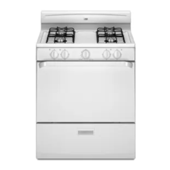
30" (76.2 CM) FREESTANDING GAS RANGE
ESTUFA AUTÓNOMA A GAS DE 30" (76,2 CM)
To the installer: Please leave this instruction book with the unit.
To the consumer: Please read and keep this book for future
reference.
W10121806B
INSTALLATION INSTRUCTIONS
with standard clean oven
INSTRUCCIONES DE INSTALACIÓN
con horno de limpieza estándar
Table of Contents..................................................2
Índice.....................................................................2
Para el instalador: favor de dejar este manual de instrucciones
con la unidad.
Para el consumidor: favor de leer y guardar este manual para
futura referencia.
Advertisement
Table of Contents

Related Manuals for Estate TGP300TQ


Summary of Contents for Estate TGP300TQ
- Page 1 INSTALLATION INSTRUCTIONS 30" (76.2 CM) FREESTANDING GAS RANGE INSTRUCCIONES DE INSTALACIÓN ESTUFA AUTÓNOMA A GAS DE 30" (76,2 CM) To the installer: Please leave this instruction book with the unit. To the consumer: Please read and keep this book for future reference.
-
Page 2: Table Of Contents
TABLE OF CONTENTS RANGE SAFETY ... 2 INSTALLATION REQUIREMENTS ...4 Tools and Parts ... 4 Location Requirements... 4 Gas Supply Requirements ... 5 INSTALLATION INSTRUCTIONS ...8 Unpack Range ...8 Install Anti-Tip Bracket ...8 Verify Anti-Tip Bracket Location ...9 Level Range ...9 Make Gas Connection ...9... - Page 3 If using a ball valve, it shall be a T-handle type. ■ A flexible gas connector, when used, must not exceed 3 feet. A child or adult can tip the range and be killed. Connect anti-tip bracket to rear range foot. Reconnect the anti-tip bracket, if the range is moved.
-
Page 4: Installation Requirements
5" (12.7 cm) beyond the bottom of the cabinets. ■ All openings in the wall or floor where range is to be installed must be sealed. ■ Do not seal the range to the side cabinets. - Page 5 30" (76.2 cm) minimum clearance between the top of the cooking platform and the bottom of an unprotected wood or metal cabinet. IMPORTANT: If installing a range hood or microwave hood combination above the range, follow the range hood or microwave hood combination installation instructions for dimensional clearances above the cooktop surface.
-
Page 6: Gas Supply Requirements
The rigid pipe must be level with the range connection. All strains must be removed from the supply and fuel lines so range will be level and in line. ■ Must include a shutoff valve: The supply line must be equipped with a manual shutoff valve. - Page 7 1/2 psi (3.5 kPa). Line pressure testing at 1/2 psi gauge (14" WCP) or lower The range must be isolated from the gas supply piping system by closing its individual manual shutoff valve during any pressure testing of that system at test pressures equal to or less than...
-
Page 8: Installation Instructions
Repeat with the other 2 corners. Place them lengthwise on the floor behind the range to support the range when it is laid on its back. Using 2 or more people, firmly grasp the range and gently lay it on its back on the cardboard corners. -
Page 9: Verify Anti-Tip Bracket Location
2. Place level on rack and check levelness of range, first side to side; then front to back. 3. If range is not level, pull range forward until rear leveling leg is removed from the anti-tip bracket. Use slip-joint pliers to adjust leveling legs up or down until range is level. -
Page 10: Check Operation
Typical rigid pipe connection A combination of pipe fittings must be used to connect the range to the existing gas line. Your connection may be different; according to the supply line type, size, and location. 1. Apply pipe joint compound made for use with LP gas to all pipe thread connections. -
Page 11: Check Operation Of Oven/Broil Burner
6. If the pilot flame needs adjustment, use a flat blade screwdriver and turn the adjusting screw until the flame is of the desired height. A. Adjusting screw 7. Push back on the side support rods and slowly lower the cooktop until it snaps into position. -
Page 12: Complete Installation
See “Troubleshooting” in your Use and Care Guide. ■ When the range has been on for 5 minutes, feel for heat. If you do not feel heat, turn the range off and check to see that the gas supply line shutoff valve is open. ■... -
Page 13: Gas Conversions
LP Gas Conversion WARNING Tip Over Hazard A child or adult can tip the range and be killed. Connect anti-tip bracket to rear range foot. Reconnect the anti-tip bracket, if the range is moved. Failure to follow these instructions can result in death or serious burns to children and adults. -
Page 14: Pilot And By-Pass Screws Conversion
5. Set them aside. 6. Locate LP gas orifice spuds for top burners in the bag containing literature included with the range. Four LP gas spuds are stamped “67.” 7. Remove the natural gas orifice spuds from the valve using a 3/8"... -
Page 15: Complete Conversion
A. Pilot screw B. By-pass screw 10. Locate the LP gas pilot screw in the bag containing literature included with the range. One LP gas pilot screw is stamped “15”. 11. Remove natural gas pilot screw with a flat blade screwdriver, turning counterclockwise. -
Page 16: Natural Gas Conversion
To Convert Gas Pressure Regulator WARNING Tip Over Hazard A child or adult can tip the range and be killed. Connect anti-tip bracket to rear range foot. Reconnect the anti-tip bracket, if the range is moved. Failure to follow these instructions can result in death or serious burns to children and adults. -
Page 17: Pilot And By-Pass Screws Conversion
6. Set the front panel aside and locate the oven thermostat. 7. Locate the natural gas by-pass screw in the bag containing literature included with the range. One natural gas by-pass screw is stamped “76”. 8. Remove the LP gas by-pass screw with a flat blade screwdriver, turning counterclockwise. - Page 18 NOTES...
-
Page 19: Seguridad De La Estufa
Su seguridad y la seguridad de los demás es muy importante. Hemos incluido muchos mensajes importantes de seguridad en este manual y en su electrodoméstico. todos los mensajes de seguridad. Este es el símbolo de advertencia de seguridad. Este símbolo le llama la atención sobre peligros potenciales que pueden ocasionar la muerte o una lesión a usted y a los demás. - Page 20 ADVERTENCIA: Para su seguridad, la información en este manual debe ser observada para minimizar el riesgo de incendio o explosión, o para prevenir daños a propiedades, heridas o la muerte. – No almacene o use gasolina u otros líquidos y vapores inflamables cerca de éste u otro aparato electrodoméstico.
-
Page 21: Requisitos De Instalación
Herramientas y piezas Reúna las herramientas y piezas necesarias antes de comenzar la instalación. Lea y siga las instrucciones provistas con cualquiera de las herramientas enlistadas aquí. Herramientas necesarias ■ Nivel ■ Trinquete de accionamiento de 3/8" ■ Cinta para medir ■... - Page 22 Requisitos de instalación adicionales para las casas rodantes La instalación de esta estufa debe ajustarse al Estándar de seguridad y construcción de casas fabricadas, Título 24 CFR, Parte 3280 (anteriormente conocido como Estándar federal para la seguridad y construcción de casas rodantes, Título 24, HUD Parte 280).
-
Page 23: Requisitos Del Suministro De Gas
Requisitos del suministro de gas ADVERTENCIA Peligro de Explosión Use una línea de suministro de gas nueva con aprobación de CSA International. Instale una válvula de cierre. Apriete firmemente todas las conexiones de gas. Si se conecta a un suministro de gas L.P., la presión no debe exceder una columna de agua de 36 cm (14") y debe ser verificada por una persona calificada. - Page 24 Regulador de la presión de gas Deberá usarse el regulador de la presión de gas suministrado con esta estufa. Para el funcionamiento adecuado, la presión de entrada al regulador deberá ser como se indica a continuación: Gas natural: Presión mínima: 5" WCP Presión máxima: 14"...
-
Page 25: Instrucciones De Instalación
INSTRUCCIONES DE INSTALACIÓN Desempaque la estufa ADVERTENCIA Peligro de Peso Excesivo Use dos o más personas para mover e instalar la estufa. No seguir esta instrucción puede ocasionar una lesión en la espalda u otro tipo de lesiones. 1. No use la agarradera de la puerta del horno para levantar o mover la estufa. -
Page 26: Verificación De La Ubicación Del Soporte Anti-Vuelco
6. Martille los sujetadores de plástico en los orificios. 7. Alinee los orificios del soporte anti-vuelco con los orificios en el piso. Sujete el soporte anti-vuelco con los tornillos provistos. Según el espesor del piso, es posible que necesite tornillos más largos para sujetar el soporte al contrapiso. -
Page 27: Verifique El Funcionamiento
Conexión típica de la tubería rígida Se debe usar una combinación de tubos de unión para conectar la estufa a la línea de suministro de gas existente. Su conexión puede ser distinta, de acuerdo con el tipo de línea de suministro, tamaño y ubicación. -
Page 28: Verifique El Funcionamiento Del Guemaden De Asan/Del Horno
6. Si se necesita regular las llamas piloto, use un destornillador de hoja plana y gire el tornillo de ajuste hasta que la llama tenga la altura deseada. A. Adjusting screw 7. Empuje nuevamente las barras laterales de soporte y baje lentamente la superficie de cocción hasta que encaje en su posición. -
Page 29: Complete La Instalación
8. Cuando la luz piloto permanezca encendida, vuelva a colocar el espaciador de llama, la bandeja inferior del horno y las parrillas. NOTA: La luz piloto permanecerá encendida después de que se apague el horno. El quemador del horno deberá encenderse la próxima vez que se seleccione la temperatura en la perilla de control del horno. -
Page 30: Conversiones De Gas
ADVERTENCIA Peligro de Explosión Use una línea de suministro de gas nueva con aprobación de CSA International. Instale una válvula de cierre. Apriete firmemente todas las conexiones de gas. Si se conecta a un suministro de gas L.P., la presión no debe exceder una columna de agua de 36 cm (14") y debe ser verificada por una persona calificada. -
Page 31: Conversión De Tornillos De Desvío Y Piloto
Cómo convertir los quemadores de superficie 1. Quite las parrillas de la superficie de cocción. 2. Levante la superficie de cocción sosteniéndola por las esquinas frontales hasta que las barras laterales de soporte encajen en su posición. 3. Quite los tornillos que sujetan cada quemador dual. A. -
Page 32: Complete La Conversión
6. Coloque el panel frontal a un lado y ubique el termostato del horno. A. Termostato del horno 7. Ubique el tornillo de desvío de gas LP en la bolsa que contiene el manual incluido en la estufa. Un tornillo de desvío de gas LP está... -
Page 33: Conversión De Gas Natural
Conversión de gas natural Cómo convertir el regulador de la presión del gas ADVERTENCIA Peligro de Vuelco Un niño o un adulto puede volcar accidentalmente la estufa y resultar muerto. Conecte el soporte anti-vuelco a la pata trasera de la estufa. Si traslada de lugar la estufa, vuelva a conectar el soporte anti-vuelco. -
Page 34: Conversión De Tornillos De Desvío Y Piloto
11. Vuelva a colocar las parrillas. Cómo convertir el quemador del horno 1. Abra la puerta del horno y saque las parrillas, charola y esparcidor de llama del horno; déjelos a un lado. 2. Levante el quemador del horno. El tornillo del orificio está detrás del obturador de aire del quemador del horno. - Page 35 NOTAS...
- Page 36 W10121806B ©2007 Whirlpool Corporation Printed in Mexico All rights reserved. Impreso en México Todos los derechos reservados. 09/2007...
Need help?
Do you have a question about the TGP300TQ and is the answer not in the manual?
Questions and answers