Table of Contents
Advertisement
Quick Links
Advertisement
Table of Contents

Related Manuals for Dahua IPC-HFW2531T-ZS-27135


Summary of Contents for Dahua IPC-HFW2531T-ZS-27135
- Page 1 HD IR Vari-Focal Fixed Network Camera Quick Start Guide Version 1.0.2...
- Page 2 Welcome Thank you for purchasing our network camera! This quick start guide is designed to be a reference tool for your system. Please keep this start guide well for future reference. Please open the accessory bag to check the items one by one in accordance with the list below. Contact your local retailer ASAP if something is missing or damaged in the bag.
- Page 3 Thunder-proof device is recommended to be adopted to better prevent thunder. The grounding studs of the product are recommended to be grounded to further enhance the reliability of the camera. 6. Daily Maintenance Please shut down the device and then unplug the power cable before you begin daily maintenance work.
-
Page 4: Table Of Contents
Table of Contents Framework ........................... 1 Device External Cable ....................1 Framework and Dimension ..................1 Device Installation ........................3 Quick Configuration Tool ......................6 Overview ........................6 Operation ........................6 Web Operation ..........................8 Network Connection ..................... 8 Login and Main Interface ..................... 8 Appendix Toxic or Hazardous Materials or Elements ............... -
Page 5: Framework
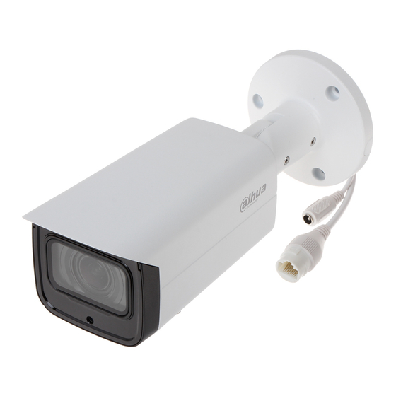
1 Framework 1.1 Device External Cable You can refer to the following figure for device external cable information. See Figure 1-1 Figure 1-1 Please refer to the following sheet for detailed information. Port Port Name Connection Note Ethernet Network port Connect to standard Ethernet cable. - Page 6 Please refer to the following figure for dimension information. The unit is mm. See Figure 1-2 and Figure 1-3. Figure 1-2 Dimension illustration 1 Figure 1-3 Dimension illustration 2...
-
Page 7: Device Installation
2 Device Installation Note: Please make sure the installation surface can min support the 3X weight of the camera and the bracket. Step 1 Open accessories bag, take out installation position map and stick it to designated surface where you will install the device (wall or ceiling). Step 2 Dig a hole according to position of hole on installation position map. - Page 8 Figure 2-2 Step 6 Use inner hex screwdriver to loosen adjusting screw shown in Figure 2-2. Step 7 Adjust the device in all possible directions, and set its monitoring direction. Step 8 Use inner hex screwdriver to tighten the adjusting screws. Figure 2-3...
- Page 9 Step 9 Screw out the pan head screw (shown in Figure 2-3) by cross head screwdriver and take off the lower cover. Step 10 Adjust the lens focus lever and set its monitoring direction more accurately by external focus. Step 11 Use cross head screwdriver to tighten the pan head screws.
-
Page 10: Quick Configuration Tool
3 Quick Configuration Tool 3.1 Overview Quick configuration tool can search current IP address, modify IP address. At the same time, you can use it to upgrade the device. Please note the tool only applies to the IP addresses in the same segment. 3.2 Operation Step 1 Double click the “ConfigTools.exe”... - Page 11 Step 3 If you want to modify the device IP address without logging in the device web interface, you can go to the configuration tool main interface to set. In the configuration tool search interface (Figure 3-1), please select a device IP address and then double click it to open the login interface.
-
Page 12: Web Operation
4 Web Operation This series network camera products support the Web access and management via PC. Web includes several modules: Monitor channel preview, system configuration, alarm and etc. 4.1 Network Connection Please follow the steps listed below for network connection. ... - Page 13 Figure 4- 2 Web login If it is your first time to log in, system pops up warning information to ask you whether install web plug-in or not after you logged in for one minute. For detailed plug-in installation, please refer to the Web Operation Manual included in the resource CD.
-
Page 14: Appendix Toxic Or Hazardous Materials Or Elements
Appendix Toxic or Hazardous Materials or Elements Component Name Toxic or Hazardous Materials or Elements Cr VI PBDE ○ ○ ○ ○ ○ ○ Circuit Board Component ○ ○ ○ ○ ○ ○ Device Construction Material ○ ○ ○ ○ ○...
Need help?
Do you have a question about the IPC-HFW2531T-ZS-27135 and is the answer not in the manual?
Questions and answers