
Subscribe to Our Youtube Channel
Related Manuals for Fluke MicroScanner MS-POE


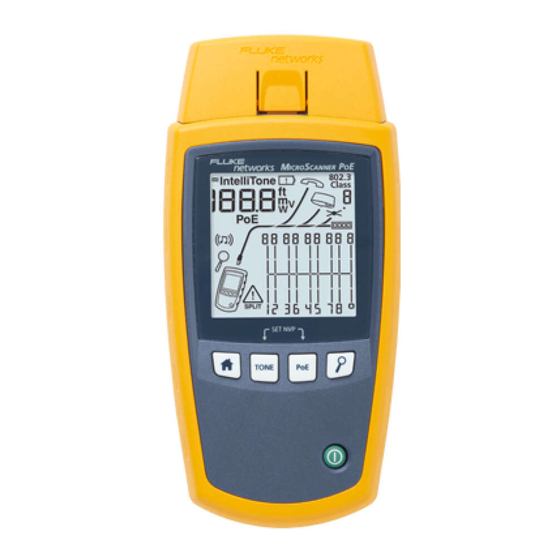
Summary of Contents for Fluke MicroScanner MS-POE
- Page 1 MicroScanner Series ™ Cable Verifiers Users Manual March 2019 ©2019 Fluke Corporation All product names are trademarks of their respective companies.
- Page 2 MH and Li-Ion batteries, cables or other peripherals are all considered parts or accessories. The warranty extends only to the original buyer or end user customer of a Fluke Networks authorized reseller, and does not apply to any product which, in Fluke Networks’...
-
Page 3: Table Of Contents
Contents Title Page Introduction ..................................1 Registration ................................... 2 Contacting Fluke Networks ..............................2 Symbols ....................................2 Safety Information ................................ 4 MicroScanner PoE Features ..............................7 MicroScanner PoE Display Features ............................. 9 MicroScanner Features ................................ 11 MicroScanner Display Features ............................13 Auto Shutoff .................................. - Page 4 MicroScanner Series Cable Verifiers Users Manual Typical Causes of Opens ............................17 Short on Twisted Pair Cabling ............................18 Typical Causes of Shorts ............................18 Crossed Wires ................................. 19 Crossed Pairs ................................... 19 Typical Causes of Crossed Pairs ..........................19 Split Pair ..................................
- Page 5 Contents MicroScanner ................................38 MicroScanner PoE ................................39 Using the Toner ..................................46 Toning in IntelliTone Mode (optional IntelliTone probe required) ................46 Analog Toner Mode (optional tone probe required) ....................49 Using the SmartTone Function ............................. 50 Using the IntelliTone Cable Map Function (optional IP200 probe required) ..............51 Calibrating Length Measurements ............................
- Page 6 MicroScanner Series Cable Verifiers Users Manual Test Modes ..................................59 Performance Specifications ............................59 Regulatory Information ..............................61...
- Page 7 Figures Figure Page High Voltage Display Examples ........................6 MicroScanner PoE Features ........................... 7 MicroScanner PoE Display Features....................... 9 MicroScanner Features ..........................11 MicroScanner Display Features ........................13 Connecting a Remote ID Locator in a Confined Area or to an RJ11 Jack........... 15 Connecting to Twisted Pair Network Cabling ....................
- Page 8 MicroScanner Series Cable Verifiers Users Manual Active Ethernet Port Detected........................25 Inactive Ethernet Port Detected ........................26 Details for a Short (MicroScanner screen shown) ..................27 Details for Terminated and Open Wire Pairs....................28 Using Multiple Remote ID Locators (MicroScanner PoE shown) ..............30 Connecting to a Telephone Network Wired in a Star Topology ..............
- Page 9 List of Figures Analog Toner Mode Display .......................... 49 Using the Toner with the IP200 IntelliTone Cable Map Function ............... 52 Replacing the Tester’s Batteries ........................55...
- Page 10 MicroScanner Series Cable Verifiers Users Manual viii...
-
Page 11: Introduction
• and detect network services. IntelliTone function works with an optional Fluke ™ Networks IntelliTone probe to help you locate and The testers do the following: isolate cables behind walls, at patch panels, or in bundles. -
Page 12: Registration
See explanations in the manual. troubleshooting tips, and other support services. To register, fill out the online registration form on the Fluke Networks On the tester’s display this symbol indicates a cable fault or voltage on the cable. -
Page 13: Safety Information
• Use only replacement parts that are approved by EMC approval for Korea. Fluke Networks. Class A Equipment (Industrial Broadcasting & • Communication Equipment). Do not touch voltages > 30 V AC rms, 42 V AC peak, or 60 V DC. - Page 14 MicroScanner Series Cable Verifiers Users Manual examples of this display. Disconnect the tester if it temperatures above 50 °C. If the batteries are detects high voltage. not removed, battery leakage can damage the • Product. Do not use the Product around explosive gas, •...
- Page 15 WSafety Information • Have an approved technician repair the Product. • Do not put metal objects into connectors. • Before using the optional IntelliTone probe, read the safety information in the probe’s documentation. Positive Negative MicroScanner PoE MicroScanner EGK29.EPS Figure 1. High Voltage Display Examples...
-
Page 16: Microscanner Poe Features
MicroScanner Series Cable Verifiers Users Manual MicroScanner PoE Features EGK32.EPS Figure 2. MicroScanner PoE Features... - Page 17 MicroScanner PoE Features On/off key. Modular jack for connecting to telephone and twisted pair network cable. The jack accepts 8-pin modular : Turns on the toner. (RJ45) and 6-pin modular (RJ11) connectors. : Starts the cable test. ...
-
Page 18: Microscanner Poe Display Features
MicroScanner Series Cable Verifiers Users Manual Detail screen indicator. See page 27. MicroScanner PoE Display Features Tone mode indicator. See page 46. G H I Power over Ethernet mode indicator. See page 38. Numeric display with feet/meters indicator. MicroScanner PoE also shows watts or volts when it detects 802.3 compliant (W) or passive (V) PoE. - Page 19 MicroScanner PoE Display Features 802.3 Class and the 7-segment display show the maximum class of PoE available (802.3 classes 0 through 8). See page 39. Indicates a short on the cable. See pages 18 and 37. Ethernet port indicator. See page 25. ...
-
Page 20: Microscanner 2 Features
MicroScanner Series Cable Verifiers Users Manual MicroScanner Features EGK01.EPS Figure 4. MicroScanner Features... - Page 21 MicroScanner Features F-connector for connecting to 75 Ω coaxial cable. On/off key. : Scrolls through screens and changes settings. Modular jack for connecting to telephone and twisted In toner mode, these keys cycle through the IntelliTone pair network cable.
-
Page 22: Microscanner 2 Display Features
MicroScanner Series Cable Verifiers Users Manual Detail screen indicator. See page 27. MicroScanner Display Features Indicates which port is active, the RJ45 port ( ) or the coaxial port ( Tone mode indicator. See page 46. ... -
Page 23: Auto Shutoff
Auto Shutoff Wiremap diagram. For opens, the number of segments Changing the Length Units lit for the wire pair indicates the approximate distance Hold down while turning on to the fault. The rightmost segments indicate the the tester. -
Page 24: Using The Wiremap Adapter And Remote Id Locators
MicroScanner Series Cable Verifiers Users Manual Using the Wiremap Adapter and Remote ID Locators Terminating twisted pair cabling with the standard Universal adapter (8-pin and 4-pin) wiremap adapter or optional remote ID locators lets the tester detect all types of wiremap faults. Without this termination, the tester cannot detect crossed wires or crossed pairs. -
Page 25: Testing Twisted Pair Cabling
Testing Twisted Pair Cabling Testing Twisted Pair Cabling Turn on the tester. MicroScanner : If the tester is already on and in coaxial test mode ( ), press to switch to twisted pair test Patch panel mode ( Connect the tester and wiremap adapter or ID locator to the cabling as shown in Figures 7 through 21. -
Page 26: Open On Twisted Pair Cabling
MicroScanner Series Cable Verifiers Users Manual Open on Twisted Pair Cabling Typical Causes of Opens • Wires connected to wrong pins at connector or Figure 8 shows an open on wire 4. punchdown blocks Notes • Faulty connections If only one wire in a pair is open and a wiremap •... -
Page 27: Short On Twisted Pair Cabling
Testing Twisted Pair Cabling Short on Twisted Pair Cabling Typical Causes of Shorts • Damaged connector. Figure 9 shows a short between wires 5 and 6. The shorted • wires flash to indicate the fault. The cable length is 75.4 m. Damaged cable. -
Page 28: Crossed Wires
MicroScanner Series Cable Verifiers Users Manual Crossed Wires Crossed Pairs Figure 10 shows that wires 3 and 4 are crossed. The the pin Figure 11 shows that pairs 1,2 and 3,6 are crossed. The pin numbers flash to indicate the fault. Cable length is numbers flash to indicate the fault. -
Page 29: Split Pair
Testing Twisted Pair Cabling Split Pair Figure 12 shows a split pair on 3,6 and 4,5. The split pair flashes to indicate the fault. The cable length is 75.4 m. In a split pair, continuity from end to end is correct, but is made with wires from different pairs. -
Page 30: Telephone Voltages Detected
MicroScanner Series Cable Verifiers Users Manual Telephone Voltages Detected Figure 13 shows that telephone voltage is detected on pair 4,5. Length is not shown because the voltage interferes with length measurements. Warning The tester is not intended to be connected to active telephone inputs, systems, or equipment, including ISDN devices. - Page 31 Testing Twisted Pair Cabling Telephone Telephone voltage icon voltage icon Positive wire (tip) Negative wire (ring) HIGH Ω MicroScanner PoE MicroScanner EGK11.EPS Figure 13. Telephone Voltages Detected...
-
Page 32: Bridge Tap Detected
MicroScanner Series Cable Verifiers Users Manual Bridge Tap Detected Figure 14 shows a bridge tap detected at about 53.2 m. Only the first bridge tap detected is reported. The distance to a bridge tap is approximate because multiple reflections from the bridge tap interfere with length measurements. Note Bridge taps more than 328 ft (100 m) from the tester or taps less than 16 ft (5 m) long may not be... - Page 33 Testing Twisted Pair Cabling HIGH Ω MicroScanner PoE MicroScanner EGK12.EPS Figure 14. Bridge Tap Detected...
-
Page 34: Ethernet Port Detected
MicroScanner Series Cable Verifiers Users Manual Ethernet Port Detected The tester can detect active and inactive Ethernet ports, as shown in Figures 15 and 16. Ethernet port icon. Port speed for an active port: • MicroScanner : The speeds are 10, 100, or 1000 megabits per second. - Page 35 Testing Twisted Pair Cabling Ethernet port icon. Cable length. Dashes are shown if the tester cannot measure the length. This can occur if the port does not produce reflections. Length may fluctuate or be obviously too high if the port’s impedance fluctuates or varies from the cable’s impedance.
-
Page 36: Viewing Details For A Wire Pair
MicroScanner Series Cable Verifiers Users Manual Viewing Details for a Wire Pair To see details for each wire pair, use to move through the screens. In this mode, the tester continuously tests only the wire pair you are viewing. Figures 17 and 18 show examples of these screens. - Page 37 Testing Twisted Pair Cabling EGK37.EPS EGK14.EPS Pair 3,6 is 67.7 m long and is terminated with the wiremap Open on pair 4,5 at 48.1 m. The open could be on one or adapter. both wires. Figure 18. Details for Terminated and Open Wire Pairs...
-
Page 38: Using Multiple Remote Id Locators
MicroScanner Series Cable Verifiers Users Manual Using Multiple Remote ID Locators Using multiple remote ID locators helps you identify multiple network connections at a patch panel, as shown in Figure 19. The display in Figure 19 shows that the tester is connected to the cable terminated with remote ID locator number 3. - Page 39 Testing Twisted Pair Cabling Patch panel Locator # 2 Locator # 3 Remote ID locators connected to wall outlets Locator # 4 Locator # 5 EGK04.EPS Figure 19. Using Multiple Remote ID Locators (MicroScanner PoE shown)
-
Page 40: Connecting To Telephone Networks Wired In Star Topologies
MicroScanner Series Cable Verifiers Users Manual The tester cannot measure length past the bridge tap Connecting to Telephone Networks Wired in because reflections from the bridge tap connections Star Topologies interfere with measurements. Telephone cables wired in a star topology (Figure 20) are connected together at a bridge tap at the distribution If you connect the tester to the bridge tap, the tester center. - Page 41 Testing Twisted Pair Cabling Distribution center Common connection RJ11 patch Wall to bridge tap cord outlets RJ11 patch cord Wiremap adapter Note: For a correct length reading, connect the tester and wiremap adapter as shown. See “Connecting to Star Topologies” for details. EGK16.EPS Figure 20.
-
Page 42: Connecting To Telephone Networks Wired In Bus Topologies
MicroScanner Series Cable Verifiers Users Manual If you are unsure which outlet is the last in the bus, do the Connecting to Telephone Networks Wired in Bus following: Topologies Telephone cables wired in a bus topology (Figure 21) Connect the wiremap adapter or ID locator to the connect the wall outlets in series. - Page 43 Testing Twisted Pair Cabling Distribution center Connection to bus Wall outlets RJ11 patch cord RJ11 patch cord Wiremap adapter Note: You can swap the locations of the tester and wiremap adapter. EGK17.EPS Figure 21. Connecting to a Telephone Network Wired in a Bus Topology...
-
Page 44: Testing Coaxial Cabling (Microscanner 2 )
MicroScanner Series Cable Verifiers Users Manual Testing Coaxial Cabling (MicroScanner Connection to Turn on the tester. service MicroScanner : Press to switch to coaxial test mode Connect the tester and wiremap adapter or ID locator to the cabling as shown in Figure 22. Coaxial patch cords For cabling not terminated with an F-connector, use an adapter or hybrid patch cord to connect to the cabling. -
Page 45: Results For A Good Coaxial Cable
Testing Coaxial Cabling (MicroScanner Results for a Good Coaxial Cable Open on Coaxial Cabling Figure 23 shows a good coaxial cable 38.4 m long and Figure 24 shows an open 12.1 m from the tester. terminated with remote ID number 3. EGK21.EPS Figure 24. -
Page 46: Short On Coaxial Cabling
MicroScanner Series Cable Verifiers Users Manual Short on Coaxial Cabling Unknown Termination on Coaxial Cabling Figure 25 shows a short 12.1 m from the tester. Figure 26 shows a cable connected to a device at the far end, such as a television, CATV service, VCR, DVD player, satellite dish, splitter, or antenna. -
Page 47: Detecting Power Over Ethernet
Detecting Power Over Ethernet Detecting Power Over Ethernet To select PoE mode, press until PoE appears on the display. In PoE mode, the tester solicits PoE on pairs 1,2-3,6 and 4,5- 7,8. The tester may activate a PoE source and will not be damaged by PoE. -
Page 48: Microscanner Poe
MicroScanner Series Cable Verifiers Users Manual MicroScanner PoE Notes To select PoE mode, press PoE sources do not always meet the wattage specification for their class. The display shows (searching) while the tester looks for PoE. The tester will verify the maximum power available if the source’s port is configured to respond to MicroScanner PoE uses the 802.3af, at, and bt standards at requests at the hardware layer only. - Page 49 Detecting Power Over Ethernet Single- and Dual-Signature Sources For single- and dual-signature sources, the MicroScanner PoE tester shows the maximum class of power available and the standard wattage for that class. See Figures 28 through 30. Table 2 on page 43 shows wattages and other information for the PoE classes.
- Page 50 MicroScanner Series Cable Verifiers Users Manual The wattage specified for the PoE class ( ). Table 2 802.3 on page 43 shows wattages and other information Class for the PoE classes. The magnifying glass blinks when the tester detects ...
- Page 51 Detecting Power Over Ethernet 802.3 802.3 Class Class HIGH Ω HIGH Ω EGK35.EPS The wattage specified for the PoE class ( ). Table 2 (dual signature): The tester detects shows wattages and other information for all the PoE dual signature PoE.
- Page 52 MicroScanner Series Cable Verifiers Users Manual Table 2. PoE Classes Input Power to Output Power from Power Powered Device Sourcing Equipment Powered Device Class Number (watts) (watts) Type IEEE Standard 3.84 802.3af (2-pair PoE) 6.49 25.5 802.3at (PoE+) 802.3bt (4-pair PoE, 4PPoE, PoE++) 802.3bt (higher-power PoE)
- Page 53 Detecting Power Over Ethernet If the Display Shows 0.0 W Note If a PoE source does not supply power to a port, the If the display shows 0.0 W, and you quickly connect MicroScanner PoE tester shows 0.0 W and PoE flashes on the tester to another port, the display might the display.
- Page 54 MicroScanner Series Cable Verifiers Users Manual Passive Sources For passive sources, the MicroScanner PoE tester shows the voltage it measures on the powered pairs, as shown in Figure 32. The voltage detected on the pairs shown. 802.3 Class (passive) shows when the tester detects a passive power source.
-
Page 55: Using The Toner
MicroScanner : Press to select twisted pair ( ) or coaxial ( ) cable. Use the tester’s IntelliTone mode with an optional Fluke ™ Networks IP100 or IP200 tone probe. The digital IntelliTone Press until , IntelliTone and a scrolling... - Page 56 MicroScanner Series Cable Verifiers Users Manual Note If you cannot locate the IntelliTone signal on 2-conductor cables, the cable may be shorted. Use the tester to check for shorts. See pages 16 and 18. Turn the probe’s rotary switch to (isolate).
- Page 57 Using the Toner Locating Cables Isolating Cables Wall outlet Volume control EGK24.EPS Figure 34. Using the Toner in IntelliTone Mode...
-
Page 58: Analog Toner Mode (Optional Tone Probe Required)
MicroScanner Series Cable Verifiers Users Manual Analog Toner Mode (optional tone probe required) Refer to Figure 35. Turn on the tester, then connect the tester to the cable. MicroScanner : Press to select twisted pair or coaxial cable. ... -
Page 59: Using The Smarttone Function
Using the Toner Press until appears on the display. Using the SmartTone Function Use the SmartTone function when you have trouble ™ Press to select the analog toner mode locating a cable. This function changes the toner’s song (IntelliTone disappears from the display). -
Page 60: Using The Intellitone Cable Map Function (Optional Ip200 Probe Required)
MicroScanner Series Cable Verifiers Users Manual Press until appears on the display. Using the IntelliTone Cable Map Function IntelliTone mode is indicated by IntelliTone and a (optional IP200 probe required) scrolling pattern of 1s and 0s on the display. See Figure The tester’s IntelliTone function works with an optional IP200 probe’s cable map function to verify wiring at the far The probe’s LEDs light in sequence to indicate the... -
Page 61: Calibrating Length Measurements
Calibrating Length Measurements Calibrating Length Measurements The tester uses an NVP value (nominal velocity of propagation) and the signal delay through the cable to calculate length. The tester’s default NVP values are usually accurate enough to verify length; however, you can increase the accuracy of length measurements by adjusting the NVP to a specified or actual value. -
Page 62: Setting The Nvp To A Specified Value
MicroScanner Series Cable Verifiers Users Manual Connect a known length of the cable to be tested to the Setting the NVP to a Specified Value tester’s twisted pair or coaxial connector. To enter the NVP value specified by the manufacturer: Notes ... -
Page 63: Maintenance
Use only specified replacement parts for user- before replacing the battery. replaceable items. • • Use only the correct type of batteries, properly Use only Fluke Networks authorized service installed in the case, to power the tester. centers. Typical battery life: Cleaning •... -
Page 64: Checking The Tester's Version, Serial Number, And Mac Address
: The first and second half of the tester’s MAC address. To exit this mode, turn the tester off. Learn More The Fluke Networks Knowledge Base answers common questions about Fluke Networks products and provides EGK28.EPS articles on cable testing techniques and technology. -
Page 65: If Something Seems Wrong With The Tester
If something seems wrong with the tester, refer to Table 3. If Table 3 does not help you solve a problem with the tester, contact Fluke Networks for additional help. If possible, have the tester’s version and serial number. For warranty information, refer to the warranty at the beginning of this manual. -
Page 66: Options And Accessories
MicroScanner Series Cable Verifiers Users Manual Options and Accessories For the latest list of options and accessories visit the Fluke Specifications Specifications apply at 23 C (73 F), unless otherwise noted. Environmental Specifications 32 °F to 113 °F (0 C to 45 Operating temperature -4 °F to +140 °F (-20... -
Page 67: General Specifications
Specifications General Specifications Shielded 8-pin modular jack accepts 8-pin modular (RJ45) and 4-pin modular (RJ11) plugs. Test connectors MicroScanner : F-connector for coaxial cable. 60 V Maximum input voltage Battery type: 2 AA (NEDA 15A, IEC LR6) alkaline batteries Power Battery life: •... - Page 68 MicroScanner Series Cable Verifiers Users Manual Test Modes Measures length, verifies wiremap, identifies remote ID locators, and detects Ethernet ports. Cable test Shows results on one screen. Generates Intellitone and normal analog toning signals ™ Tone MicroScanner : Solicits and detects the presence of 802.3af compatible PoE (Power over Ethernet) devices.
- Page 69 10 Mbps, 100 Mbps, 1 Gbps, 2.5 Gbps, 5 Gbps, and 10 Gbps. MicroScanner PoE uses LLDP on 10/100 Mbps Ethernet networks to discover and negotiate LLDP negotiation PoE when necessary. Supports toning and cable mapping with a Fluke Networks digital IntelliTone probe. ™ Tone generator Generates four tones compatible with typical analog probes.
- Page 70 MicroScanner Series Cable Verifiers Users Manual Regulatory Information This equipment generates, uses, and can radiate radio frequency energy, and, if not installed and used in accordance with the manual, may cause interference to radio communications. It has been tested and found to comply with the limits for a Class A digital device pursuant to Part 15, Subpart J of the FCC rules, which are designed to provide reasonable protection against such interference...
Need help?
Do you have a question about the MicroScanner MS-POE and is the answer not in the manual?
Questions and answers