Table of Contents
Advertisement
Available languages
Available languages
Advertisement
Chapters
Table of Contents

Related Manuals for Fluke MicroNetBlink Kit


Summary of Contents for Fluke MicroNetBlink Kit
- Page 1 M I C R O T O O L S ICRO LINK ™...
- Page 2 MicroProbe User Guide Manuel Utilisateur Benutzer Handbuch Manuale per l'utente Guía del Usuario Manual do Utilizador 2947-4511-01 Rev. 01 11/2001 © 2001 Fluke Networks, Inc. All rights reserved. Printed in USA. All product names are trademaaarks of their respective companies.
-
Page 4: Table Of Contents
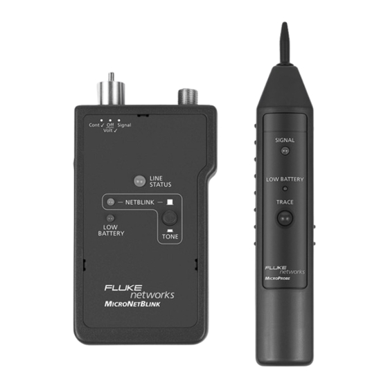
Congratulations on your purchase of and/or M ICRO LINK ICRO ROBE The M is a practical network installa- ICRO LINK tion and troubleshooting tool that flashes a hub light, features a unique tone signal, two test leads, 8- conductor twisted pair cable (RJ45), and a 4-con- ductor modular cable (RJ11) to test standard Cat 5 cabling, COAX cables, and bare wires. - Page 5 & M ICRO LINK ICRO ROBE Inductive Probe with Non- conductive tip 3-Postion Switch: Continuity Test Off/ Volt Check Volume Signal Control Signal LED F-Type Connector for tone tracing Ring/Tip Polarity Test LED Netblink/ Netblink Tone Button Battery RJ11Connector for Continuity Test and Trace Button Tip/Ring Signal.
-
Page 6: Micronetblink Features
Features ICRO LINK • 2-position NetBlink/Tone button for flashing a hub light or toning • Toggle switch to control 3 modes of operation • 2-color LED indicator for telephone line polarity, continuity and voltage testing • 8-pin modular cable (RJ45) for flashing hub lights, tracing cables, and locating jacks •... -
Page 7: Battery
Battery requires a 9 Volt Alkaline battery. ICRO LINK requires a 9 Volt Alkaline battery. ICRO ROBE The low Battery LED will light up when a low battery condition is detected. Using the units with a low battery may effect the test accuracy. -
Page 8: Micronetblink Tests
Tests ICRO LINK Flashing the Hub Light Status 1. Set the toggle switch to the Signal position. 2. Plug the 8-position cable (RJ45) into the jack to be tested. 3. Verify that the button on the face of the in the NETBLINK position. ICRO LINK IS 4. -
Page 9: Identifying Telephone Line Polarity
Identifying Telephone Line Polarity 1. Set the toggle switch to the Off/Volt ü position. 2. Connect the black alligator test lead to the TIP (+) connection, usually green or blue. 3. Connect the red alligator test lead to the RING (-) connection, usually red or marked R. -
Page 10: Testing For Low Voltage
4. Set the toggle switch to Cont ü to answer the line or go off-hook. Note: The brightness of the GREEN line status is an indicator of the amount of telephone loop current present while the toggle switch is in the Cont ü... -
Page 11: Testing Continuity
Testing Continuity 1. Set the toggle switch to the Cont ü position. 2. Connect the red and black alligator test leads to the circuit to be tested. The LED indicator will light up: GREEN indicates a low resistance path from RED LEAD (+) to BLACK LEAD(-) GREEN (DIM) indicates that there is a high resistance path... -
Page 12: Appendix A
• To test terminated coaxial cables, connect the red test lead to the connector housing and the black test lead to center pin, or connect the red test lead to the connector housing and the black test lead to the ground. Appendix A ICRO LINK... - Page 13 • Pen-style casing • Special inductive plastic tip • One push-button TRACE switch • One battery low LED indicator • One speaker and one LED for signal detection • One rotary volume level switch MicroNetBlink / MicroProbe...
- Page 14 Merci d’avoir acheté M et/ou ICRO LINK ICRO ROBE est un outil d’installation et de dépan- ICRO LINK nage réseau très pratique offrant de nombreuses fonc- tionnalités destinées au test de câblages de Catégo- rie 5 standard, de câbles coaxiaux et de fils nus : cli- gnotement du témoin du hub, signal à...
- Page 15 et M ICRO LINK ICRO ROBE Sonde inductive avec pointe non conductrice Commutateur à 3 positions : Test de continuité Contrôle Off/Volt Contrôle du Signal volume Voyant de signal Connecteur de type F pour le suivi de la tonalité Voyant de Ring/Tip Polarity Test Bouton...
-
Page 16: Fonctionnalités De Micronetblink
Fonctionnalités de M ICRO LINK • Bouton NetBlink/Tone à deux positions pour le clignote- ment d’un voyant de hub ou l’émission de tonalités. • Commutateur à bascule pour contrôler les 3 modes de fonctionnement • Voyant bicolore pour les tests de continuité, de tension et de polarité... -
Page 17: Pile
Pile nécessite l’emploi d’une pile alcaline ICRO LINK de 9 volts. présente les mêmes exigences. ICRO ROBE Le témoin de batterie faible s’allume lorsque le dispositif détecte un état de décharge avancée de la pile. Utiliser les unités dans ces conditions risque d’affecter la précision des tests. -
Page 18: Clignotement Du Voyant D'état Du Hub
Tests M ICRO LINK Clignotement du voyant d’état du hub 1. Placez le commutateur à bascule en position Signal. 2. Branchez le câble à 8 positions (RJ-45) sur la prise à tester. 3. Assurez-vous que le bouton situé à l’avant de l’unité... -
Page 19: Identification De La Polarité De La Ligne Téléphonique
Identification de la polarité de la ligne téléphonique 1. Placez le commutateur à bascule en position Off/Volt ü. 2. Connectez le fil de test à pinces crocodiles noir à la connexion TIP (+), laquelle est généralement de couleur verte ou bleue. 3. -
Page 20: Détection De Basse Tension
L’alternance des couleurs VERTE et ROUGE (clignotement rapide) indique un signal d’appel. 4. Placez le commutateur à bascule en position Cont ü pour répondre ou décrocher le combiné. Remarque : l’intensité d’un voyant d’état de ligne VERT indique la quantité de courant de boucle présent lorsque le commutateur à... -
Page 21: Test De La Continuité
Test de la continuité 1. Placez le commutateur à bascule en position Cont ü. 2. Connectez les fils de test à pinces crocodiles rouges et noirs au circuit à tester. Le voyant s’allume : Un voyant VERT indique un circuit basse résistance entre le FIL ROUGE (+) et le FIL NOIR (-) Un voyant VERT (PÂLE) indique la présence d’un circuit haute résistance. -
Page 22: Annexe A
Annexe A ICRO LINK • Dimensions : 115 mm x 63 mm x 26 mm • Poids : 19 g • Alimentation : pile alcaline CC de 9 V (non fournie) • +/- 30 cm de fil de test noir et rouge à pinces crocodiles pour les tests de continuité... - Page 23 • Etui de type porte-stylo • Pointe plastique inductive spéciale • Un bouton TRACE • Un voyant de batterie faible • Un haut-parleur et un voyant pour la détection du signal • Un bouton de réglage du volume MicroNetBlink / MicroProbe...
- Page 24 Herzlichen Glückwunsch zum Kauf von und/oder M ICRO LINK ICRO ROBE Das M ist ein praktisches Gerät zur ICRO LINK Netzwerkinstallation und Fehlerbehebung in Netz- werken. Es umfasst eine Hub-Blinkanzeige, eine Funktion zur Erzeugung von Signaltönen, zwei Prüf- leitungen, ein achtadriges Twisted-Pair-Kabel (RJ45) und ein vieradriges modulares Kabel zum Prüfen von Kat.-5-Standardkabeln, Koaxialkabeln und Blank-verdrahtungen.
- Page 25 und M ICRO LINK ICRO ROBE Induktive Sonde mit nichtleitender Prüfspitze Umschalter mit 3 Positionen: Kontinuitätsprüfung Spannungsprüfsignal Lautstärke- regelung Signal-LED Anschluss vom Typ F LED-Anzeige für Ring/Tip- Signalton- Polaritäts- verfolgung prüfung Netblink-LED Netblink-/ Signal- tontaste Batterie LED RJ11Connector for Continuity Test and Taste zur Tip/Ring Signal.
-
Page 26: Funktionen Von Micronetblink
Funktionen von ICRO LINK • NetBlink-/Signalton-Umschalter für blinkende Hub-Anzeige oder Signalton • Kippschalter zur Steuerung der 3 Betriebsmodi • Zweifarbige LED-Anzeige zum Prüfen der Telefonleitungs- polarität, Kontinuität und Spannung • 8-adriges modulares Kabel (RJ45) für blinkende Hub- Anzeigen, Kabelverfolgung und Buchsenerkennung •... -
Page 27: Batterie
Batterie Für das M ist eine 9-Volt-Alkali- ICRO LINK batterie erforderlich. Für das M ist eine 9-Volt-Alkalibatterie ICRO ROBE erforderlich. Die Batterieanzeige leuchtet auf, wenn eine niedrige Batterieladung festgestellt wird. Eine niedrige Batterieladung kann sich auf die Prüfgenauigkeit der Geräte auswirken. Wenn die Geräte länger als einen Monat nicht in Gebrauch sind, sollte die Batterie ausgetauscht werden. -
Page 28: Blinkanzeige Für Hub-Status
-Tests ICRO LINK Blinkanzeige für Hub-Status 1. Stellen Sie den Kippschalter auf die Position Signal. 2. Schließen Sie das 8-adrige Kabel (RJ45) an der zu testenden Buchse an. 3. Prüfen Sie, ob sich die Taste vorne am in der Position NETBLINK ICRO LINK befindet. -
Page 29: Erkennen Der Telefonleitungspolarität
Achtung: Schließen Sie das Gerät nicht an einen aktiven Wechselstromkreis an, der in diesem Modus eine Spannung von über 24 V hat. Erkennen der Telefonleitungspolarität 1. Stellen Sie den Kippschalter auf die Position Off/Volt ü (Aus/Spannung ü). 2. Schließen Sie die Prüfleitung mit der schwar- zen Krokodilklemme am Anschluss TIP (+) an, der normalerweise grün oder blau markiert ist. -
Page 30: Prüfen Auf Niederspannung
GRÜN (HELLGRÜN) bedeutet, dass die Telefonleitung richtig verdrahtet ist, wobei das Telefon gerade verwendet wird (Hörer abgehoben). ROT bedeutet, dass die Telefonleitung eine vertauschte Polarität aufweist. 3. Verwenden Sie eine zweite Telefonleitung, um die zu prüfende Nummer anzuwählen. ROT und GRÜN (rasch blinkend) gibt ein Anrufsignal an. -
Page 31: Prüfen Der Kontinuität
3. Schließen Sie die Prüfleitung mit der schwar- zen Krokodilklemme an den anderen Draht des Kabel- oder Leitungspaars an. Wenn die Anzeige für den LEITUNGSSTATUS GRÜN aufleuchtet, dann ist die schwarze Prüfleitung an eine NEGATIVE (-) Gleich- spannung (GS) angeschlossen. Wenn die Anzeige für den LEITUNGSSTATUS ROT aufleuchtet, dann ist die schwarze Prüfleitung an eine POSITIVE (+) Spannung... -
Page 32: Prüfen Der Kontinuität Mittels Signalton
Prüfen der Kontinuität mittels Signalton 1. Stellen Sie den Kippschalter auf die Position Signal. 2. Schließen Sie die Prüfleitungen an das zu prüfende Paar an. 3. Bei Verwendung eines Handapparats oder einer Sprechgarnitur am anderen Ende berühren Sie das (die) Drahtende(n) mit der (den) Klemme(n). - Page 33 Anhang A ICRO LINK • Abmessungen: 115 mm x 63 mm x 26 mm • Gewicht: 19 g • Stromversorgung: 9-V-Alkalibatterie, GS (nicht im Lieferumfang enthalten) • Jeweils ca. 30 cm lange Prüfleitungen mit roter bzw. schwarzer Krokodilklemme für Spannungs- und Kontinuitätsprüfung •...
- Page 34 Congratulazioni per aver acquistato e/o M ICRO LINK ICRO ROBE è un pratico strumento per installa- ICRO LINK zioni e risoluzione dei problemi di rete, dotato di un indicatore hub lampeggiante, un esclusivo segnale acustico, due cavi test, un cavo twistato a 8 condut- tori (RJ45) e un cavo modulare a 4 conduttori (RJ11) per testare cavi standard Cat 5, coassiali e scoper- ti.
- Page 35 ICRO LINK E ICRO ROBE IAgo induttivo con punta in materiale non conduttivo Commutatore a 3 posizioni: Test di continuità Controllo Off/verifica tensione volume Segnale segnale Connettore tipo F per tracciatura test di segnale polarità acustico Ring/ Pulsante Netblink/ segnale Netblink acustico batteria...
-
Page 36: Funzionalità Di Micronetblink
Funzionalità di M ICRO LINK • Pulsante NetBlink/segnale acustico, a 2 posizioni, per lampeggiamento indicatore hub o sintonizzazione • Commutatore per controllare 3 modalità di funzionamento • Indicatore LED bicolore per i test di polarità, continuità e tensione della linea telefonica •... -
Page 37: Batteria
Batteria funziona con una batteria alcalina ICRO LINK da 9 Volt. M funziona con una batteria ICRO ROBE alcalina da 9 Volt. Il LED batteria scarica si accende quando viene rilevata una condizione di batteria scarica. L’uso delle unità con la batteria scarica può pregiudicare la precisione dei test. -
Page 38: Test Di Micronetblink
Test di ICRO LINK Lampeggiamento dell’indicatore di stato 1. Impostare il commutatore nella posizione Signal. 2. Collegare il cavo a 8 posizioni (RJ45) nel jack da testare. 3. Verificare che il pulsante sul lato anteriore di M sia in posizione NETBLINK. ICRO LINK 4. -
Page 39: Identificazione Della Polarità Della Linea Telefonica
Attenzione: In questa modalità non effettuare il collegamento a un circuito c.a. attivo, con tensione superiore a 24 V. Identificazione della polarità della linea telefonica 1. Impostare il commutatore nella posizione Off/ Volt ü. 2. Collegare il cavo test nero con estremità a coccodrillo alla connessione TIP (+), di solito verde o blu. -
Page 40: Test Bassa Tensione
VERDE (MENO INTENSO) indica un circuito telefonico cablato corretto e già in uso o sganciato ROSSO indica un circuito telefonico a polarità invertita 3. Utilizzare una seconda linea telefonica per comporre il numero che si sta testando. ROSSO e VERDE (lampeggianti rapidamente) indicano un segnale di chiamata. -
Page 41: Test Di Continuità
Se lo stato della linea è VERDE, il cavo test nero è collegato a una tensione NEGATIVA (-) c.c. Se lo stato della linea è ROSSO, il cavo test nero è collegato a una tensione POSITIVA (+) c.c. Se lo stato della linea è ROSSO/VERDE, è presente la tensione c.a.. -
Page 42: Test Cavi Coassiali
La ricezione del segnale acustico è un’indicazione di continuità. Tutti i test di cui sopra sono validi esclusivamente per spinotti modulari per la linea 1 (cavi rossi e verdi). Test cavi coassiali • Per testare cavi coassiali senza terminazione, collegare il cavo test rosso alla schermatura esterna e il cavo test nero al conduttore centrale oppure collegare il cavo test rosso alla schermatura esterna e il cavo test nero alla... -
Page 43: Appendice A
Appendice A ICRO LINK • Dimensioni: 4,53” x 2,49” x 1,03” 115mm x 63mm x 26mm • Peso: 19g • Alimentazione: Batteria c.c. alcalina da 9 V (non in dotazione) • 2 cavi test rossi e neri con estremità a coccodrillo, ciascuno da 0,3 m (1 ft.), per i test di tensione e continuità... - Page 44 ¡Enhorabuena por haber comprado ICRO LINK ICRO ROBE es una práctica herramienta para la ins- ICRO LINK talación y la solución de problemas de redes;hace par- padear la luz de un nodo, incluye una señal de tono acústico exclusiva, dos conductores de comprobación, cable de par trenzado de 8 conductores (RJ45) y un cable modular de 4 conductores (RJ11) para la com- probación de cableado estándar de Cat 5, cables...
- Page 45 ICRO LINK ICRO ROBE Sonda inductiva con punta no conductora Conmutador de 3 posiciones: Comprobación de continuidad, Control del Off/Volt, Señal volumen Señal LED Conector tipo F para segui- Ring/Tip miento del Polarity tono Test LED Botón Tono/ NetBlink NetBlink LED de batería baja...
- Page 46 Características de M ICRO LINK • Botón de 2 posiciones NetBlink/Tono para hacer parpadear la luz del nodo o emitir tonos • Conmutador para controlar los 3 modos de funcionamien- • Indicador LED bicolor para comprobar la polaridad de la línea telefónica, la continuidad y la tensión.
-
Page 47: Micronetblink Y Microprobe
Batería funciona con una pila alcalina de ICRO LINK 9 voltios. M funciona con una batería ICRO ROBE alcalina de 9 voltios. El LED de batería baja se encenderá cuando detecte que el nivel de la batería es bajo. La precisión de las pruebas puede verse afectada si se utiliza una batería con un nivel de carga bajo. -
Page 48: Parpadeo De La Luz De Estado Del Nodo
Pruebas con M ICRO LINK Parpadeo de la luz de estado del nodo 1. Seleccione con el conmutador la posición Signal (Señal) 2. Enchufe el cable de 8 posiciones (RJ45) en el jack que se va a comprobar. 3. Compruebe que el botón de la parte delantera de M se encuentra en... -
Page 49: Identificación De La Polaridad De La Línea Telefónica
Identificación de la polaridad de la línea telefónica 1. Seleccione con el conmutador la posición Off/ Volt ü. 2. Conecte el conductor de pruebas de pinza de cocodrilo negro a la conexión TIP (+), normalmente de color verde o azul. 3. -
Page 50: Comprobación De Bajo Voltaje
telefónico con cableado correcto que ya está en uso. En ROJO indica que el circuito telefónico tiene la polaridad invertida. 3. Utilice otra línea telefónica para marcar el número que se está comprobando. ROJO y VERDE (con un parpadeo rápido) indica que hay una señal de llamada. -
Page 51: Comprobación De La Continuidad
conductor de pruebas negro se encuentra conectado a un voltaje NEGATIVO(-) de CC Si el ESTADO de la LÍNEA está en ROJO, el conductor de pruebas negro se encuentra conectado a un voltaje POSITIVO (+) Si el ESTADO DE LÍNEA aparece en ROJO/ VERDE, hay voltaje de CA. -
Page 52: Pruebas Coaxiales
La recepción del tono indica la continuidad. Todas las pruebas anteriormente mencionadas pueden aplicarse a los conectores modulares de sólo una línea (conductores rojos y verdes). Pruebas coaxiales • Para comprobar cables coaxiales sin termina- ción, conecte el conductor de prueba rojo al blindaje externo y el conductor de prueba negro al conductor central, o bien conecte el conductor de prueba rojo al blindaje externo y... - Page 53 Appendix A ICRO LINK • Dimensiones: 4,53 x 2,49 x 1,03 pulgadas 115 mm x 63 mm x 26 mm • Peso: 19 g • Alimentación eléctrica: Pila alcalina de 9V de CC (no incluida) • 0,3 m de conductor de pruebas con pinza de cocodrilo rojo y otro negro para comprobar el voltaje y la continuidad.
- Page 54 Parabéns pela sua compra do M ICRO LINK e/ou do M ICRO ROBE é uma prática ferramenta de solu- ICRO LINK ção de problemas instalação e instalação de rede que possui uma luz piscante de hub , um sinal sonoro ex- clusivo, duas pontas de teste, um cabo de par trança- do (RJ-45) de 8 condutores, e um cabo modular (RJ- 11) de 4 condutores, para testar cabeamentos padrão...
-
Page 55: Micronetblink E Microprobe
ICRO LINK ICRO ROBE Ponta indutiva com ponta Não- Condutiva Chave de 3 Posições: Teste de Continuidade Desligado/ Verificação de Tensão Sinal Controle de Volume Indicador Luminoso de Sinal Conector Tipo F para acompanha- Indicador mento de Luminoso de sinal acústico Teste de Toque/Ponta Botão... -
Page 56: Características Do Micronetblink
Características do M ICRO LINK • Botão NetBlink/Sinal Acústico de 2 posições para acendimento piscante de uma luz de hub ou emissão de sinal acústico • Chave alternada para controle de 3 modos de operação • Indicador luminoso bicolor para teste de polaridade de linha telefônica, continuidade e tensão •... -
Page 57: Bateria
Bateria necessita de uma bateria ICRO LINK alcalina de 9V. necessita de uma bateria alcalina ICRO ROBE de 9V. O indicador luminoso de carga baixa de bateria acendese quando for detectada uma condição de carga baixa. O uso do MICROSCANNER com bateria fraca pode afetar a precisão do teste. -
Page 58: Piscando A Luz De Estado De Hub
Testes do M ICRO LINK Piscando a Luz de Estado de Hub 1. Posicione a chave alternada em Signal. 2. Conecte o cabo RJ45 de 8 posições ao conector a ser testado. 3. Verifique se o botão frontal do está na posição NETBLINK. ICRO LINK 4. -
Page 59: Identificando A Polaridade De Linhas Telefônicas
Identificando a Polaridade de Linhas Telefônicas 1. Coloque a chave alternada na posição Off/ ü. Volt 2. Conecte a ponta de teste jacaré preta à conexão TIP (+), normalmente verde ou azul. 3. Conecte a ponta de teste jacaré vermelha à conexão RING (-), normalmente vermelha ou marcada com um ‘R’. -
Page 60: Testes De Baixa Tensão
4. Coloque a chave alternada na posição Cont ü para atender a chamada ou para tirar a linha do gancho. Nota: A intensidade do estado VERDE da linha é um indicador da intensidade de corrcircuitos telefônicos podem ser perigosas, nunca toque o metal das pontas de teste enquanto o estiver conectado a uma linha ICRO... -
Page 61: Testes De Continuidade Utilizando Sinais Acústicos
O indicador luminoso se acenderá: VERDE indica um caminho de baixa resistência entre a PONTA VERMELHA (+) e a PONTA PRETA (-) VERDE (FRACO) indica um caminho de alta resistência DESLIGADO indica um circuito aberto. Testes de Continuidade Utilizando Sinais Acústicos 1. -
Page 62: Apêndice A
Apêndice A ICRO LINK • Dimensões: 4,53" x 2,49" x 1,03" 115mm x 63mm x 26mm • Peso: 19g • Alimentação: bateria alcalina de 9VCC (não inclusa) • 1 pé (304,8 mm) de fios com pontas de teste jacaré vermelha e preta, para testes de tensão e continuidade •... - Page 63 MicroNetBlink / MicroProbe...
- Page 64 Fluke Networks authorized resellers shall extend this warranty on new and unused products to end-user customers only but have no authority to extend a greater or different warranty on behalf of Fluke Networks. Warranty support is available only if product is purchased through a Fluke Networks authorized sales outlet or Buyer has paid the applicable international price.
- Page 65 Everett, WA 98206-0777 6-01 Registration Registering your product with Fluke Networks gives you access to valuable information on product updates, troubleshooting tips, and other support services. To register, fill out and return the postage- paid card provided, or fill out the online registration form on the Fluke Networks website.
- Page 66 M I C R O T O O L S...
Need help?
Do you have a question about the MicroNetBlink Kit and is the answer not in the manual?
Questions and answers