Table of Contents
Advertisement
Quick Links
CC85XXDK Quick Start Guide
1. Kit Contents
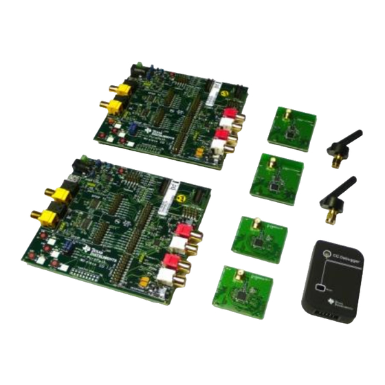
The following items are included in the
CC85XXDK:
2 x Purepath Wireless AudioEB
1 x CC Debugger
2 x CC85xxEM
2 x CC85xx-CC2590EM
2 x 2.4 GHz Antennas
Cables
Documentation
The RF boards in this kit are FCC and IC
certified and tested/comply with
ETSI/R&TTE over temperature from 0 to
+35°C. The antenna, W1010 from Pulse,
is a ¼ wave dipole antenna with 2 dBi
gain.
4. Plug Slave EM into PPW
Audio EB
Connect the CC85xxEM or the CC85xx-
CC2590EM
marked
SLAVE
attached on the backside of the board.)
These boards are pre-programmed with
slave firmware. Attach the antenna to the
SMA connector.
2. Purpose of this Quick Start
Guide
This quick start guide will provide step-by-
step instructions showing how to set up an
audio link between two wireless units
provided in the development kit. The
procedure is the same regardless of which
evaluation module is being used, i.e.
either the C85xxEM or the CC85xx-
CC2590EM.
The
EMs
are
pre-programmed
firmware
to
stream
(Master) line-in input of one AudioEB to
the (Slave) line-out and headphone output
on the other AudioEB. Please follow step
2 to 9. For the latest firmware revision see
step 10.
For more details on CC85xx, see the
product folder of the CC8520 [1].
Caution! To minimize risk of
injury,
components during operation
if symbolized as hot.
Caution!
ESD sensitive components.
Handle with care to prevent
permanent damage.
5. Connect Audio Cables to the
Master
Connect an audio source (CD-player,
MP3-player or similar) to the line-in input
of the AudioEB with CC85xxEM or
CC85xx-CC2590 with the "MASTER" label
plugged in.
The CC85xx-CC2590EM and CC85xxEM
with
the
"MASTER"
programmed with firmware which sets up
the onboard TLV320AIC3101 codec [2] to
use analog input on the PPW AudioEB.
(label
3. Plug Master EM into PPW
Audio EB
with
audio from
the
avoid
touching
Connect the CC85xxEM or the CC85xx-
CC2590EM
attached on the backside of the board).
The kit contains
These boards are pre-programmed with
master firmware. Attach the antenna to
the SMA connector.
6. Connect Audio Cables to the
Slave
Connect an amplifier to line out or connect
a headphone to the mini jack of the
AudioEB with the CC85xxEM or the
CC85xx-CC2590 with the "SLAVE" label
plugged in.
The CC85xx-CC2590EM and CC85xxEM
label
are
pre-
with
the
programmed with firmware which sets up
the onboard TLV320AIC3101 codec [2] to
use line out and headphone output of the
PPW AudioEB.
SWRU252B
September 2012
marked
MASTER
(label
"SLAVE"
label
are
pre-
Advertisement
Table of Contents

Related Manuals for Texas Instruments CC85-CC2590EM Series


Summary of Contents for Texas Instruments CC85-CC2590EM Series
- Page 1 SWRU252B September 2012 CC85XXDK Quick Start Guide 1. Kit Contents 2. Purpose of this Quick Start 3. Plug Master EM into PPW Guide Audio EB This quick start guide will provide step-by- step instructions showing how to set up an audio link between two wireless units provided in the development kit.
- Page 2 You can now turn on your audio source and start testing! 10. PurePath Wireless A. More information B. References Configurator On Texas Instruments’ Low-Power RF [1] CC8520 product page web site you will find information about our www.ti.com/product/cc8520 latest products,...
- Page 3 EVALUATION BOARD/KIT/MODULE (EVM) ADDITIONAL TERMS Texas Instruments (TI) provides the enclosed Evaluation Board/Kit/Module (EVM) under the following conditions: The user assumes all responsibility and liability for proper and safe handling of the goods. Further, the user indemnifies TI from all claims arising from the handling or use of the goods.
- Page 4 For EVMs annotated as FCC – FEDERAL COMMUNICATIONS COMMISSION Part 15 Compliant Caution This device complies with part 15 of the FCC Rules. Operation is subject to the following two conditions: (1) This device may not cause harmful interference, and (2) this device must accept any interference received, including interference that may cause undesired operation.
- Page 5 For EVMs annotated as IC – INDUSTRY CANADA Compliant This Class A or B digital apparatus complies with Canadian ICES-003. Changes or modifications not expressly approved by the party responsible for compliance could void the user’s authority to operate the equipment. Concerning EVMs including radio transmitters This device complies with Industry Canada licence-exempt RSS standard(s).
- Page 6 Also, please do not transfer this product, unless you give the same notice above to the transferee. Please note that if you could not follow the instructions above, you will be subject to penalties of Radio Law of Japan. Texas Instruments Japan Limited (address) 24-1, Nishi-Shinjuku 6 chome, Shinjukku-ku, Tokyo, Japan http://www.tij.co.jp 【ご使用にあたっての注意】...
- Page 7 EVALUATION BOARD/KIT/MODULE (EVM) WARNINGS, RESTRICTIONS AND DISCLAIMERS For Feasibility Evaluation Only, in Laboratory/Development Environments. Unless otherwise indicated, this EVM is not a finished electrical equipment and not intended for consumer use. It is intended solely for use for preliminary feasibility evaluation in laboratory/development environments by technically qualified electronics experts who are familiar with the dangers and application risks associated with handling electrical mechanical components, systems and subsystems.
Need help?
Do you have a question about the CC85-CC2590EM Series and is the answer not in the manual?
Questions and answers