Table of Contents

Subscribe to Our Youtube Channel
Summary of Contents for Youkey Q7
- Page 1 Pocket Ultrasound System INSTRUCTION FOR USE Model:Q7 IMPORTANT! Read and understand this manual before operating the equipment. After reading, keep this manual in an easily accessible place. WuHan Youkey Bio-Medical Electronics Co., Ltd.
-
Page 2: Table Of Contents
Contents Maintenance and repair service ....................6 Intellectual Property Statement ....................6 Version information ........................6 Product Information ........................7 After-sales service unit: ......................7 Safety precautions ........................8 Security classification ..................... 8 Symbol definition ......................8 Security symbol ....................... 8 Safety warning information ..................... - Page 3 3.3 Connection ........................27 3.3.1 Wifi Connection ....................27 3.3.2 USB Connection....................27 4 Detailed operation introduction .................... 27 4.1 Image mode ........................27 4.2 Image parameter adjustment ..................27 4.3 Parameter adjustment about B mode ................28 4.3.1 B mode image parameter..................28 4.3.2 B mode image optimization ................
- Page 4 8.1 Enter or exit puncture mod ..................... 52 8.2 Puncture lead calibration ....................52 9 Acoustic output description ...................... 53 9.1 biological effect ......................53 9.2 Caution use declaration ....................53 9.3 ALARA principle(As Low As Reasonably Achievable) ..........53 9.4 MI/TI description ......................
- Page 5 Introduction This manual describes the operation of the ultrasonic diagnostic equipment. In order to ensure the safe operation of the system, please read and understand the contents of the manual before using the system This specification is formulated and explained by the company The company reserves the right to change the contents of the instruction manual without prior notice Important statement!
-
Page 6: Maintenance And Repair Service
Maintenance and repair service The standard warranty period of this product is 2 years, and the main warranty period is about 1 years. The warranty period from the product warranty card fill in the attached "date of installation" date, the warranty card is the only certificate calculation warranty period. Within the warranty period, the product is provide with free customer service;... -
Page 7: Product Information
Product Information Product name:Pocket ultrasound system Product Model: Q7 Name of the registrant: WuHan Youkey Bio-Medical Electronics Co., Ltd Registered address:No.1, Floor 2, Building 7, Block B, No.818, High-tech Avenue, Donglaxin Technical Development Zone, Wuhan City, China Production enterprise name: WuHan Youkey Bio-Medical Electronics Co., Ltd Production address (residence): 2nd Floor, Dingxin Industry park, Jiayuan Road, East Lake Development Zone, 430074 Wuhan, PEOPLE’S REPUBLIC OF CHINA... -
Page 8: Safety Precautions
1 Safety precautions 1.1 Security classification ⚫ According to the type of anti electric shock: Internal power supply, where the adapter is Class 1; ⚫ According to the degree of anti electric shock: Type BF application part; ⚫ According to the protection degree of harmful liquid: The Main unit is IPX4, transducer is IPX7 ⚫... -
Page 9: Safety Warning Information
Security Detailed description symbol Nonionizing radiation 1.4 Safety warning information In order to ensure the safety of the patient and the operator, the following safety rules should be strictly observed in the use of the wireless ultrasonic probe. Do not use the scanner in an environment containing combustible gas, such as an anesthetic gas, hydrogen, or flammable liquid, :... - Page 10 Matters needing attention in clinical examination technology: ➢ This equipment can only be operated by qualified medical personnel. ➢ This manual does not introduce a clinical examination technique. It is necessary to select the correct inspection techniques according to the professional training knowledge and clinical experience.
-
Page 11: Warning Labels
In order to prevent abnormal probe function, read the following safety precautions: After each ultrasonic examination, the ultrasonic coupling agent on the surface of the probe should be thoroughly cleaned. Otherwise, the ultrasonic coupling agent will be solidified on the probe head, which will affect the quality of the ultrasound image. -
Page 12: Product Overview
2 Product overview 2.1Intended use Pocket Ultrasound System is intended for use by a qualified physician for ultrasound evaluation. Specific clinical applications and exam types include: Abdominal, Obstetrics, Gynaecology, Small Parts (breast, thyroid, etc), Peripheral Vascular, Urology. 2.2 Contraindication Pocket Ultrasound System is not intended for ophthalmic use or any use causing the acoustic beam to pass through the eye. -
Page 13: Power Condition
Port 8080-8084 IP range 192.168.254.10-192.168.254.200 Operating WindowsXP、7、8、10 or Android5.0 or above system 1.Windows system is recommended to install the top anti-virus software, such software takes up less resources, runs smoothly, and does not conflict, enough to protect system security. Antivirus 2.The general Android system brand equipment has built-in software security procedures, no need to download;... -
Page 14: Probe Outline Dimensions And Weight
liquid condensation in the circuit board, there is the risk of short circuit. 3. Do not operate the unit in an environment with flammable or explosive liquids, vapors or gases such as oxygen or hydrogen. Do not use the scanner in an environment containing combustible gas, such as an anesthetic gas, hydrogen, or flammable liquid, such as ethanol. -
Page 15: Standard Configuration
2.4.1 Standard configuration Main unit: 1 set ➢ Appendix ➢ Application Operation manual 2.4.2 Components 2.4.2.1 Optional Transducer Transducer Type of Intended Applicable Center Frequency model Transducer site frequency range C5-2Fs Large convex Gynecology body 3.5MHz 2.0~5.0MHz transducer surface obstetrics, abdominal kidney C5-2Ks... -
Page 16: Symbols Description
2.5 Symbols description This device uses the following symbol identification, the following list shows its meaning. Symbols Description Type BF application part explain:All ultrasonic probes are part of the BF application. Please refer to the instruction manual for this symbol to avoid accidents This symbol represents the product serial number This symbol represents the date of production... -
Page 17: Introduction Of Each Component Of The System
2.6 Introduction of each component of the system Serial Name Function number Transducer Transmit and receive ultrasound Scanning control and data processing Main Device Control Panel Operation control Type-C interface USB-C port for charging and data transferring... -
Page 18: Control Panel
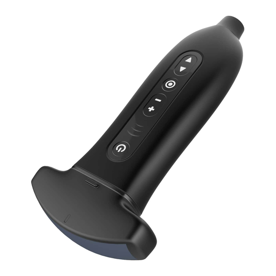
2.7 Control panel 2.7.1 Control area schematic Serial Button Key name Function number icon 1. Short press: power on / freeze / unfreeze scanner Power switch / 2. Long press >=3s: power off the scanner. freeze / thaw 3. Blue blinking, the scanner is in freezing status. button 4. -
Page 19: Basic Interface
2.8 Basic interface 2.8.1 Android application interface The interface layout diagram for the Android application is as follows: Status and information display area Freq Gain 16.cm Menu and Parameters display area Freq Gain Depth Gain 16.cm Image area Function keys 2.8.1 Interface layout diagram Status and information display area The status and information display area includes system menu, WiFi/USB connection... - Page 20 System time ➢ Displays the current system time. Check time as the image freezes when the system freezes. Menu and Image Parameter display area The areas can be divided into two parts : image mode switching area and image parameter adjustment area. B mode,click to switch to M mode, click back to B mode;...
-
Page 21: Windows Application Interface
2.8.2 Windows application interface The interface layout diagram for the Windows application is as follows: Information area Status area Image parameters and menu area Thumbnail area Zoom in on area Softkeys control area Thumbnail control area 2.8.1 Interface layout diagram Information area The information area includes manufacturer identification, patient information, hospital name, probe type, current inspection type, date, inspection time, freezing mark, etc. - Page 22 Shows the type of examination currently in use, such as the ABD. Image parameters and menu area Image parameters share this area with the menu. When a menu is not displayed on the screen, the area displays the image parameters of the current imaging modes. ➢...
-
Page 23: Information Security
Probe USB connection and selection of check Typ ➢ Electronic manual ➢ System preset ➢ Shows the current system for storage, print tasks, and exit the application. ➢ Information security 2.9.1 Forget password When the user forgets the password, the software can be reinstalled. At this time, the original password is cleared and a new password can be set. - Page 24 Two grids are always More than 75% of electricity bright One grid is always 50%~75% of electricity Battery level bright (left) indicator One grid is always 25%~50% of electricity bright (right) Slow flash 25% or less...
-
Page 25: Basic Introduction
Q7 Pocket Ultrasound System does not work when external Power supply is connected. Connect to the Type-C interface of the probe by the charging power cord as required by the standard. The external power supply system of Q7 Pocket Ultrasound System must meet the following requirements: Output:5V 2A DC internal electric source :7.4V... -
Page 26: Turn Off The Probe
Before Turn on the scanner, please carefully check or operate the following items: Serial Inspection items number Temperature, humidity and atmospheric pressure shall meet the requirements for use. The probe shall not be damaged or soiled. Clean the site and the environment. Probe cleaning and disinfection. -
Page 27: Connection
3.3 Connection 3.3.1 Wifi Connection After the machine starts, select the current scanner corresponding to the WiFi hot spot name, on the end device click to connect. 3.3.2 USB Connection Windows: Install the Windows driver in SonoiQ folder , Connect the straight USB-C to the scanner USB-C port, connect the elbow USB-C to the Windows device and you will get images immediately. -
Page 28: Parameter Adjustment About B Mode
Adjust sound power Adjust the TGC for the corresponding target area Changing gray-scale image effect Adjust dynamic range Adjust effect Adjust frame correlation Click [one key Optimization] to optimize one key Increasing frame rate of Gray- Reduce depth scale Image Adjust color gain Change the effect of blood flow image display... -
Page 29: B Mode Image Optimization
4.3.2 B mode image optimization Gain Resume The total gain of the image in the two-dimensional mode ,displays in real time on the image parameter area on the left side of the screen. Effect By increasing the brightness of the gain image, more echo signals can be observed, but at the same time, there will be more noise.。... - Page 30 Effect The larger the dynamic range, the darker the overall image, the smaller the contrast, and the greater the noise. Focus Position Resume Optimize the image of a specific depth by adjusting the location of the focus. Effect The penetration and resolution near the focal point are higher than those outside the focus.
-
Page 31: Parameter Adjustment About M Mode
Resume Color difference is used instead of gray difference to image, that is, grayscale atlas colorization. Effect Q7 pocket ultrasound system provides four different pseudo-color maps, which are effective for real-time, frozen and movie playback images. Biopsy Resume Choose and set the biopsy guide. -
Page 32: M Mode Image Optimization
4.4.2 M mode image optimization Gain Resume Adjust the gain of M mode ,displays in real time on the image parameter area on the left side of the screen. Effect By increasing the brightness of the gain image, more echo signals can be observed, but at the same time, there will be more noise.。... - Page 33 Gray Map Resume Adjust the black-and-white gray-scale contrast to optimize the image. Effect Q7 pocket ultrasound system provides 18 effects, and is effective for real-time, frozen and cine-played images. Time mark Resume Sets the display state of the time mark on the M image.
-
Page 34: Parameter Adjustment About Color Mode
4.5 Parameter adjustment about Color mode Color Doppler is used to observe the color blood flow and provide the flow direction and velocity information of the blood flow. In general, red indicates the blood flow to the probe, blue indicates the blood flow away from the probe, the brighter the color, the faster the blood flow, the darker the color, and the slower the blood flow rate. - Page 35 The low frequency noise caused by vessel wall vibration is filtered out to display the image information effectively. This function is used to adjust the cut-off frequency of the wall filter in Q7 pocket ultrasonic system. Effect May cause loss of blood flow signals.
-
Page 36: Parameter Adjustment About Power Mode
Effect Large value, priority display color image, small value, priority display black-and- white image. Resume Color image display effect parameters, according to the need to switch different atlas can get more comprehensive blood flow information. Influence This function is effective for real-time, frozen and movie playback images. Invert Resume Set the display mode of Color mode, turn over the color ruler when it is turned on,... -
Page 37: Power Mode Image Optimization
The Power mode shares the probe sound power of the B mode ,When the acoustic power is adjusted, the sound power of the two imaging modes changes synchronously. Because the Color mode is superimposed by two-dimensional (B) mode and Doppler mode, the two kinds of images change synchronously when magnifying or adjusting the depth. -
Page 38: Parameter Adjustment About Pw Mode
4.7 Parameter adjustment about PW mode PW mode (spectral Doppler mode) is used to provide the information of blood flow direction and velocity. The transverse axis of the spectrum pattern represents the time and the longitudinal axis indicates the Doppler frequency shift. PW mode has the function of distance gating, which can show the velocity, direction and nature of local blood flow at a certain depth. - Page 39 Auto Calculation Resume Set auto calculation on and off. Auto Calculation parameters Resume Set PS, ED, MD, PV, TAMAX, PPG, MPG, HR, VTI, RI, DT, AT, S/D, PI, D/S auto calculation parameters. Automatic calculation and of parameters automatic calculation Resume The spectrum Doppler waveform is recorded and the parameters are calculated.
- Page 40 Gain Resume Adjusting the output signal size of the spectrum map, the gain value is displayed in the image parameter area on the left side of the screen in real time. Effect By increasing the brightness of the gain image, more echo signals can be observed, but at the same time, there will be more noise.
-
Page 41: Measure
Wall filter Resume It is used to adjust the cut-off frequency of the wall filter in Q7 pocket ultrasonic system, and to filter the low frequency noise caused by the vibration of the vessel wall so as to display the image information effectively. Wall filter values are displayed in real time in the image parameter area on the left side of the screen. -
Page 42: Conventional Measure
5.1 Conventional measure 5.1.1 2D Conventional measure 2D conventional measurements are suitable for regular measurements of 2D images such as B, Color, Power and so on. The items of measurement are as follows: Measure item Function Distance Measure the distance between two points on an ultrasonic image. Measured the angle between the two intersecting planes on the ultrasonic Angle image. -
Page 43: Special Measuring Package
After the image freezes, the system supports movie playback and editing functions. At the same time, it supports magnification, post-processing, measurement, annotation, adding body mark and so on. Q7 pocket ultrasound system supports manual playback and automatic playback; automatic and manual playback can be switched between each other. -
Page 44: Cineloop Playback
In the image freeze state, click [Save Cine] in the SoftKey area. After you save the cineloop, you can view it locally. Annotation It is often necessary to add comments to ultrasound images during diagnosis. Q7 pocket ultrasound system supports two annotation types: typing characters and indicating arrowheads. Body mark (for Windows version) The body position of the probe and the position of the probe scanning direction are indicated by the body mark, which can help to explain the image. - Page 45 Table 1 Image performance Indexes Probe model Order Mode Project number C5-2Fs C5-2Ks L11-4Ks L11-4Gs C8-5Ks Probe nominal frequency (MHz) Deviation between acoustic working ±15 ±15 ±15 ±15 ±15 frequency and nominal frequency(%) Maximum detection ≥180 ≥170 ≥60 ≥60 ≥60 depth(mm) ≤2(depth≤80) ≤2(depth≤80)
- Page 46 Probe model Order Mode Project number C5-2Fs C5-2Ks L11-4Ks L11-4Gs C8-5Ks Depth of investigation ≥120 ≥120 ≥40 ≥40 ≥40 (mm) Relationship between color blood flow image and gray-scale coincide coincide coincide coincide coincide image of the pipe in which it is located It can be It can be...
- Page 47 Table 2 Image performance Indexes Probe model Order Mode Project number E10-4Ks Probe nominal frequency (MHz) Deviation between acoustic working frequency and ±15 nominal frequency(%) Maximum detection ≥60 depth(mm) lateral resolution ≤2 (mm) (depth≤50) Azimuthal ≤1 resolution (mm) (depth≤60) Fade zone(mm) ≤3 Slice ≤8...
-
Page 48: Probe Cover
Order Probe model Mode Project number E10-4Ks Service frequency (MHz) Depth of ≥40 investigation(mm) Velocity measurement ±20 deviation(%) Near the wall of the pipe, no Accuracy of velocity indication; center of position of Vernier pipe, maximum velocity in Doppler display sampling area Probe cover In order to reduce the spread of the disease, it is necessary to take some protective measures. -
Page 49: Check Up
7.3.1 Check up Frequently check the sockets. If any parts found damaged, repair or replace it immediately. Check acoustic lens regularly. If any bubbles found, repair or replace the broken parts right away. 7.3.2 Service life According to the manufacturer's design, production and other related documents, the service life of this probe is about 5 years. - Page 50 . water or an anti - virus solution. Immersion can cause an electric shock or malfunction. If the coupling agent is not completely removed after each detection, it will solidify and reduce the image quality of the probe. Do not place the probe in high temperature environment (over 55℃) during cleaning and disinfection.
- Page 51 Tristel Duo NCU Chlorine dioxide Tristel trio wipes system Enzymes, Chlorine Dioxide Accel® PREVention™ Wipes & RTU Hydrogen Peroxide CaviWipes isopropyl alcohol Sani-Cloth HB Germicidal Disposable Alcohol free quaternary ammonium Wipe Sani-Cloth Plus Germicidal Disposable isopropyl alcohol Cloth Cautio The probe must be cleaned after each use; n:...
-
Page 52: Puncture Guide
8 Puncture guide 8.1 Enter or exit puncture mod ⚫ Under the Windows platform, in the SoftKey area, click B mode [Image Parameter Settings], and select [puncture (on / off)]. Set [Bracket] for quick calibration. Set [guide line], depending on needle selection, A, B, and ALL. Set [linetype], have thick, medium, thin. -
Page 53: Acoustic Output Description
9 Acoustic output description The contents of this chapter for the entire system (including main unit , probe, accessories and peripherals), in order to provide relevant information to the operator output sound and how to use ALARA control principle of irradiation time and other important safety information. In addition, this chapter also includes information related to the system of acoustic output real-time display. -
Page 54: Mi/Ti Description
Users must be responsible for the safety of patients, to the use of ultrasonic, the output power of ultrasonic to choose according to the principle of ALARA. Other information about the ALARA principle and the potential biological effects of ultrasound, can see the Research Institute of medical ultrasound (AIUM) published the "medical ultrasound safety"... -
Page 55: Mi/Ti Display Instructions
(bone thermal index) skull thermal index). TIS: soft tissue thermal index applications, such as the abdomen and the heart ➢ TIB: the use of bone thermal index, such as the fetus (in late pregnancy), ➢ focused on or close to the focus of the acoustic beam in the bone TIC: Skull thermal index applications such as pediatric and adult skulls. -
Page 56: Sound Power Setting
9.5 Sound power setting Acoustical power adjustment In the frozen state of the image, the ultrasonic energy is not output. Default settings description The operator is the most important factor to control the sound output The intensity level depends on the acoustic output in the scanning area. In the fetal examination, be especially careful control of acoustic output intensity. -
Page 57: Acoustic Power Control
9.6 Acoustic power control Sound output depends on the system operator, the operator should obtain qualified under the premise of effective diagnostic image to reduce the acoustic output. There are three types of operation control and sound output control: direct control and indirect control and receiver control. ⚫... -
Page 58: Acoustic Output Limit
9.7.2 Acoustic output limit In accordance with the FDA requirements of Track 3, the acoustic output limits using the derating (or attenuation) method, as shown in the table below. The use of any probe in any mode of operation, the maximum acoustic output should be listed in the following table limits. FDA 3 Track maximum sound output limit (attenuation) (W/cm Application... -
Page 59: Uncertainty Of Measurement
9.8 Uncertainty of measurement I spta 31.2% I sppa 30.4% center frequency (f c ) Total power (W) 30.1%(5.6% Scan mode and combination mode) Peak negative pressure(pr) 15.5% 9.9 Reference literature for sound power and its safety “Bio-effects and Safety of Diagnostic Ultrasound” issued by AIUM in 1993 “Medical Ultrasound Safety”... - Page 60 +C+PW) Normal(B C5-2Fs Still Air 24.612 24.612 TF=35.528 TR=10.916 +C+PW) Normal(B C5-2Ks 24.590 24.539 TF=29.08 TR=4.541 +C+PW) Normal(B C5-2Ks Still Air 23.272 23.368 TF=32.995 TR=9.627 +C+PW) Normal(B L11-4Ks 23.140 24.330 TF = 29.421 TR =5.091 +C+PW) Normal(B L11-4Ks Still Air 22.380 23.340 TF = 34.73 TR =11.390...
-
Page 61: Electromechanical Safety Standards
10 Electromechanical safety standards The system complies with the EMC test standard IEC60601-1-2: 2007+AC:2010. Medical Electrical Equipment. General Requirements for Basic Safety and Essential Performance- Collateral Standard. Electromagnetic Compatibility. Requirements and Tests. WARNIN 1 、 The use of inappropriate accessories will reduce the performance of the product. - Page 62 The user shall install and use according to the EMC information provided by the random file. Portable and mobile RF communication equipment may affect the Q7 pocket ultrasound system to avoid strong magnetic interference, such as near microwave ovens, elevators, etc.
- Page 63 Table 2: Electromagnetic disturbance guidance and manufacturer statement This system can be used in a specified electromagnetic environment, users should ensure the use of electromagnetic environment in the following provisions. Electromagnetic Immunity test IEC 60601Test level Accord level environment - A Guide The ground must be made of wood, concrete or tile.
- Page 64 Table 3: Electromagnetic disturbance guidance and manufacturer statement This system can be used in a specified electromagnetic environment, users should ensure the use in the electromagnetic environment in the following provisions. IEC 60601 Test Electromagnetic environment - A Accord Immunity test level Guide level...
- Page 65 The radio base station (cellular and wireless) and ground mobile radio mobile phone antenna, receiver, field FM and am radio as well as TV broadcast is unable to use pure theory to accurately estimate. In order to evaluate the electromagnetic environment of fixed RF transmitter generates, should be taken into account.
- Page 66 Scanning mode: the mode of operation of an ultrasonic diagnostic device, including a series of ultrasonic pulses that generate scanning lines that do not follow the same acoustic path. Scanning mode Parameter Gain:0-100 tunable B mode Maximal acoustic output :10-100% tunable Depth:...
-
Page 67: Appendix A Names And Contents Of Toxic And Hazardous Substances Or Elements
Appendix A Names and contents of toxic and hazardous substances or elements Table:Names and contents of toxic and hazardous substances or elements Toxic Toxic or hazardous substances or elements Polybromin hazardous Hexavalent ated substances mercury cadmium phenyl lead(Pb) chromium biphenyls (Hg)... - Page 68 Time average sound intensity Decay time average sound intensity ta, α Spatial peak time average sound zpta intensity Decay time space peak time average zpta, α sound intensity Mechanical index output power Output power after attenuation α Bounded output power Pulse sound pressure square integral Peak sparse sound pressure Peak sparse sound pressure...
- Page 69 Probe :C5-2Fs Mode:B Table 201.103 Transducer Model: C5-2Fs, Operating Model: B Index label At surface Below At surface Below surface surface 0.94 0.20 0.20 Maximum index value 0.20 Index component value 0.20 Acoustic 1.56 Parameters (mW) 25.39 25.39 (mW) 14.03 14.03 (cm) (cm)
- Page 70 Probe:C5-2Fs Mode:B+M Table 201.103 Transducer Model: C5-2Fs, Operating Model: M Index label Below Below surface surface surface surface Maximum index value Index component value Acoustic Parameters Other Information Focus (mm) Operating control Depth (mm) conditions Frequency (MHz) Speed...
- Page 71 Probe:C5-2Fs Mode:B+C Table 201.103 Transducer Model: C5-2Fs, Operating Model: B+C Index label Below Below surface surface surface surface Maximum index value Index component value Acoustic Parameters Other Information Focus (mm) Operating control Depth (mm) conditions Frequency (MHz) Frequency (MHz) Mode:PW Probe:C5-2Fs Table 201.103 Transducer Model: C5-2Fs, Operating Model: PW...
- Page 72 Probe:C5-2Fs Mode:B+P Table 201.103 Transducer Model: C5-2Fs, Operating Model: B+P Index label Below Below surface surface surface surface Maximum index value Index component value Acoustic Parameters Other Information Operating Focus (mm) control conditions Depth (mm) Frequency (MHz) Frequency (MHz)
- Page 73 Probe:C5-2Ks Mode:B Table 201.103 Transducer Model: C5-2Ks, Operating Model: B Index label Below Below surface surface surface surface Maximum index value Index component value Acoustic Parameters Other Information Operating Focus (mm) control Depth (mm) conditions Frequency (MHz) Mode:B+M Probe:C5-2Ks Table 201.103 Transducer Model: C5-2Ks, Operating Model: B+M Index label Below...
- Page 74 Probe:C5-2Ks Mode:B+C Table 201.103 Transducer Model: C5-2Ks, Operating Model: B+C Index label Below Below surface surface surface surface Maximum index value Index component value Acoustic Parameters Other Information Focus (mm) Operating control Depth (mm) conditions Frequency (MHz) Frequency (MHz) Mode:B+P Probe:C5-2Ks Table 201.103 Transducer Model: C5-2Ks, Operating Model: B+P...
- Page 75 Probe:C5-2Ks Mode:PW Table 201.103 Transducer Model: C5-2Ks, Operating Model: PW Index label Below Below surface surface surface surface Maximum index value Index component value Acoustic Parameters Other Information Operating Focus (mm) control Depth (mm) conditions Frequency (MHz) Mode:B Probe:L11-4Ks Table 201.103 Transducer Model: L11-4Ks, Operating Model: B Index label Below...
- Page 76 Probe:L11-4Ks Mode:B+M Table 201.103 Transducer Model: L11-4Ks, Operating Model: M Index label Below Below surface surface surface surface Maximum index value Index component value Acoustic Parameters Other Information Focus (mm) Operating Depth (mm) control conditions Frequency (MHz) Speed Mode:B+C Probe:L11-4Ks Table 201.103 Transducer Model: L11-4Ks, Operating Model: B+C Index label...
- Page 77 Probe:L11-4Ks Mode:B+P Table 201.103 Transducer Model: L11-4KFs, Operating Model: B+P Index label Below Below surface surface surface surface Maximum index value Index component value Acoustic Parameters Other Information Focus (mm) Operating control Depth (mm) conditions B_Frequency (MHz) Frequency (MHz) Probe:L11-4Ks Mode:PW Transducer Model: L11-4Ks, Operating Model: PW Table 201.103 Index label...
- Page 78 Probe:L11-4Gs Mode:B Table 201.103 Transducer Model: L11-4Gs, Operating Model: B Index label Below Below surface surface surface surface Maximum index value Index component value Acoustic Parameters Other Information Focus (mm) Operating control Depth (mm) conditions Frequency (MHz) Mode:B+M Probe:L11-4Gs Table 201.103 Transducer Model: L11-4Gs, Operating Model: B+M Index label Below...
- Page 79 Probe:L11-4Gs Mode:B+C Table 201.103 Transducer Model: L11-4Gs, Operating Model: B+C Index label Below Below surface surface surface surface Maximum index value Index component value Acoustic Parameters Other Information Focus (mm) Operating control Depth (mm) conditions B_Frequency (MHz) Frequency (MHz) Mode:B+P Probe:L11-4Gs Transducer Model: L11-4Gs, Operating Model: B+P Table 201.103...
- Page 80 Probe:L11-4Gs Mode:PW Table 201.103 Transducer Model: L11-4Gs, Operating Model: PW Index label Below Below surface surface surface surface Maximum index value Index component value Acoustic Parameters Other Information Operating Focus (mm) control Depth (mm) conditions Frequency (MHz) Probe:C8-5Ks Mode:B Table 201.103 Transducer Model: C8-5Ks, Operating Model: B Index label Below...
- Page 81 Probe:C8-5Ks Mode:B+M Table 201.103 Transducer Model: C8-5Ks, Operating Model: B+M Index label Below Below surface surface surface surface Maximum index value Index component value Acoustic Parameters Other Information Focus (mm) Operating Depth (mm) control Frequency (MHz) conditions Speed Probe:C8-5Ks Mode:B+C Table 201.103 Transducer Model: C8-5Ks, Operating Model: B+C Index label...
- Page 82 Table 201.103 Transducer Model: C8-5Ks, Operating Model: B+P Index label Below Below surface surface surface surface Maximum index value Index component value Acoustic Parameters Other Information Focus (mm) Operating control Depth (mm) conditions B_Frequency (MHz) Frequency (MHz) Mode:PW Probe:C8-5Ks Table 201.103 Transducer Model: C8-5Ks, Operating Model: PW Index label Below...
- Page 83 Probe:E10-4Ks Mode:B Mode:B+M Probe:E10-4Ks...
- Page 84 Probe:E10-4Ks Mode:B+C Mode:B+P Probe:E10-4Ks...
- Page 85 Probe:E10-4Ks Mode:PW...
- Page 86 Legal manufacturer: WuHan Youkey Bio-Medical Electronics Co., Ltd. 2nd Floor, Dingxin Industry park, Jiayuan Road, East Lake Development District, Wuhan. 430074, PRC* Production sites: Wuhan Youkey Bio-Medical Electronics Co., Ltd. No. 3,6F, Unit 1, North Building of Xingye Building, Science and Technology Park of Wuhan...
Need help?
Do you have a question about the Q7 and is the answer not in the manual?
Questions and answers