
Subscribe to Our Youtube Channel
Related Manuals for ADTRAN 220 HTU-C


Summary of Contents for ADTRAN 220 HTU-C
- Page 1 ® HDSL 220 HTU-C Installation and Maintenance Practice Document Number: 61247001L1-5A CLEI: T1I3AAHA_ _ March 2008...
- Page 2 In no event will ADTRAN be liable for any special, incidental, or consequential damages or for commercial losses even if ADTRAN has been advised thereof as a result of issue of this document.
- Page 3 Revision History Revision Date Description March 2008 Initial release Conventions The following typographical conventions are used in this document: This font indicates a cross-reference link. indicates screen menus, fields, and parameters. This font indicates keyboard keys ( ). Keys that are to be pressed simultaneously HIS FONT NTER are shown with a plus sign (...
- Page 4 HDSL 220 Transceiver Unit for Central Office Installation and Maintenance Practice Training ADTRAN offers training courses on our products. These courses include overviews on product features and functions while covering applications of ADTRAN product lines. ADTRAN provides a variety of training options, including customized training and courses taught at our facilities or at customer sites.
-
Page 5: Table Of Contents
Instructions for Installing the 220 HTU-C........ - Page 6 220 HTU-C Span Powering Diagram ........
- Page 7 220 HTU-C Bantam Jack Arrangement........
- Page 8 HDSL 220 Transceiver Unit for Central Office Installation and Maintenance Practice This page is intentionally blank. viii 61247001L1-5A...
-
Page 9: General
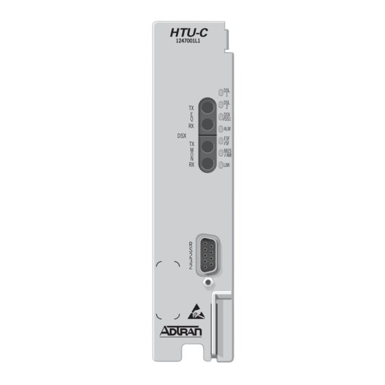
220 HTU-C GENERAL The ADTRAN 220 Transceiver Unit for Central Office (220 HTU-C) is used to deploy a repeat- erless T1 circuit using 4-wire metallic facilities. The 220 HTU-C (P/N 1247001L1) occupies one slot in a 220 office repeater shelf. The 220 HTU-C front panel is illustrated in Figure Figure 1. -
Page 10: Description
The 220 HTU-C contains an onboard fuse. If the fuse opens, it supplies –48 VDC to the fuse alarm bus and all front panel indicators turn off. This fuse is not field-replaceable. -
Page 11: Compliance
Description Compliance The 220 HTU-C is NRTL listed to the applicable UL standards for continuous use in –40°C to +50°C environmental conditions. Care should be exercised when handling equipment when temperatures at these extremes exist, as surfaces could be very cold or hot. - Page 12 NOTE The 220 HTU-C is designed to operate with a nominal operating voltage of –48 VDC and a minimum operating voltage of –40 VDC. The 220 HTU-C will not be damaged by any steady state voltage below –56.7 VDC. NOTE Current limiting protectors are not required.
-
Page 13: Hdsl Deployment Guidelines
HDSL Deployment Guidelines HDSL DEPLOYMENT GUIDELINES The ADTRAN HDSL system is designed to provide DS1 based services over loops designed to comply with carrier service area (CSA) guidelines. CSA deployment guidelines are given below. • All loops are non-loaded only. -
Page 14: Table 3. Hdsl Loss Values
HDSL 220 Transceiver Unit for Central Office Installation and Maintenance Practice Table 3. HDSL Loss Values (200kHz cable loss in dB/kft at 135 Ω) Temperature: Cable Gauge Cable Type 68° 90° 120° 3.902 4.051 4.253 Pulp 4.030 4.179 4.381 2.863 2.957 3.083 Pulp... -
Page 15: Installation
Customer Service. For more information, refer to “Appendix C, Warranty”. The 220 HTU-C plugs directly into the 220 office repeater shelf. The 220 HTU-C may be plugged into any of the 28 numbered slots in this shelf. No installation wiring is required. NOTE... -
Page 16: Line Build Out Switch
1. Hold the 220 HTU-C by the front panel while supporting its bottom edge to engage the chassis edge. 2. Align the 220 HTU-C edges to fit in the lower and upper guide grooves for the module slot. 3. Slide the 220 HTU-C into the module slot. Simultaneous thumb pressure at the top (above... -
Page 17: Front Panel Leds
Installation Front Panel LEDs LED indicators on the front panel of the 220 HTU-C provide the status of the HDSL circuit. The LED indications and descriptions are shown in Table Table 6. Front Panel LEDs Label Status Description No sync between the HTU-C and HTU-R on Loop 1/Loop 2... -
Page 18: Connections
HDSL 220 Transceiver Unit for Central Office Installation and Maintenance Practice CONNECTIONS The 220 HTU-C occupies one card slot in a 220 office repeater shelf. Power and alarm signals are provided to the card through the backplane of the shelf. DSX-1 and HDSL loop signals are connected to the shelf connector and transmitted to the corresponding slot the 220 HTU-C occupies. -
Page 19: Alarm Connections
Connections The 220 HTU-C is capable of span powering the HTU-R by applying simplex current to the local loop. From 0 to 125 mA of current is coupled onto the HDSL span to power the HTU-R and HRE when deployed. The span powering voltage is –190 volts with Loop 1 providing the... -
Page 20: Provisioning
HDSL 220 Transceiver Unit for Central Office Installation and Maintenance Practice PROVISIONING Provisioning is performed via software. For more information, refer to the “Control Port Operation” section of this practice. The provisioning settings can be viewed and manipulated through management access via the front panel RS-232 port. -
Page 21: Control Port Operation
Control Port Operation CONTROL PORT OPERATION The 220 HTU-C provides a faceplate-mounted DB9 connector that supplies an RS-232 interface for connection to a controlling terminal. The pinout of the DB9 is illustrated in Figure Pin 5 - Signal Ground (SGN) -
Page 22: User Interface
• Screen Abbreviations Menu Structure The 220 HTU-C uses a layered menu tree. Each layer of the menu tree is displayed as a menu or a screen. Menu A menu is a display that provides numbered selections that are used to navigate to related menus, modify provisioning information, or display information screens. -
Page 23: Screen Abbreviations
User Interface Screen Abbreviations Table 8 lists the abbreviations used in the screen examples shown in Figures 6 through 18. Table 8. Screen Abbreviations Abbreviation Definition Errored Seconds • DSX/DS1 – SF: Second in which a BPV or frame bit error occurs –... -
Page 24: Menu Descriptions
HDSL 220 Transceiver Unit for Central Office Installation and Maintenance Practice MENU DESCRIPTIONS The following subsections describe the 220 HTU-C menu screens. A terminal session is initiated by entering multiple space bar characters, which will determine the speed of the terminal. -
Page 25: Figure 7. Hdsl Main Menu
Menu Descriptions HDSL Main Menu The ADTRAN HDSL Main Menu, illustrated in Figure 7, is selected from the Introductory menu by pressing “ ”. Various Operation, Administrative, Maintenance, and Provisioning (OAM&P) screens may be accessed from the Main Menu. Circuit ID:HNTSVLALHDSL... - Page 26 HDSL 220 Transceiver Unit for Central Office Installation and Maintenance Practice Table 9. HDSL Main Menu Options (Continued) Option Description Function Troubleshooting This option displays the “Troubleshooting Display Screen” on page 26. Alarm History This option displays the “Alarm History Screen” on page 27.
-
Page 27: Current System Status Screens
Table 10 below. Arrows indicate the key applies to both the 220 HTU-C and HTU-R. Table 10. HDSL, DS1, and DSX-1 Key Definitions Indicator... -
Page 28: Table 11. Pair Reversal Key Definitions
Predicting performance based upon signal quality varies with each loop. Generally, a noise margin of 0 or higher will support a bit error rate of better than 10 . ADTRAN defined guide- lines that correspond to the operation of the 220 HTU-C faceplate LEDs labeled LP1 and LP2 are illustrated in Table Table 13. -
Page 29: Current System Status - Hre Screen
Menu Descriptions Current System Status - HRE Screen The Current System Status - HRE screen, illustrated in Figure 9, is selected from the Current System Status screen by typing “ ”. Type “ ” once to view current system status for HRE#1. Type “... -
Page 30: Performance History Screen
10, displays the historical HDSL and T1 performance data in several different registers. At each 15-minute interval, the performance information is transferred to the previous 15-minute performance data register. The 220 HTU-C stores performance data in 15-minute increments for the last 24-hour period. At each 24-hour interval, the performance data is transferred into the 24-hour performance data register also accessed from the Performance History screen. -
Page 31: Performance History - Hre Screen
Menu Descriptions Performance History - HRE Screen The Performance History - HRE screen, illustrated in Figure 11, is selected from the Perfor- mance History screen by typing “ ”. Type “ ” once to view the Performance History screen for HRE#1. -
Page 32: Loopback Options Menu
The Loopback Options menu, illustrated in Figure 12, displays and allows the changing of loopback settings throughout the HDSL circuit. For more information on HDSL Loopbacks, refer to “220 HTU-C Loopbacks” on page 31. Circuit ID:HNTSVLALHDSL MM/DD/YY hh:mm:ss LOOPBACK OPTIONS... -
Page 33: Self Test Options Screen
Figure 13. Self-Test Options Screen Provisioning Menu The Provisioning menu, illustrated in Figure 14, provides the option to change the 220 HTU-C provisioning settings. A full list of provisioning options can be found in Table 7 on page 12. CIRCUIT ID:... -
Page 34: Troubleshooting Display Screen
Figure 15, graphically depicts an HDSL circuit. The 220 HTU-C reviews red, yellow, and blue alarm conditions in the circuit to automatically predict where a fault is located. Once a fault location is suspected, the corre- sponding portion of the circuit on the screen will be highlighted and a message describing the failure will appear. -
Page 35: Alarm History Screen
Menu Descriptions Alarm History Screen The Alarm History screen, illustrated in Figure 16, provides detailed information on the alarm history of the HDSL and T1 spans. Information provided includes alarm location, type, first and last time/date, current status, and count. Circuit ID:HNTSVLALHDSL MM/DD/YY hh:mm:ss T1 Alarm History... -
Page 36: Set Time/Date/Circuit Id Menu
HDSL 220 Transceiver Unit for Central Office Installation and Maintenance Practice Set Time/Date/Circuit ID Menu The Set Time/Date/Circuit ID menu, illustrated in Figure 17, provides additional provisioning options. Enter the time parameters as military time (for example, enter 3:15 p.m. as 15:15:00). Enter the date parameters in MM/DD/YY format. -
Page 37: Default Options Screen
Menu Descriptions Default Options Screen The Default Options screen, illustrated in Figure 18, allows the setting of all provisioning options to the factory defaults. Circuit ID:HNTSVLALHDSL MM/DD/YY hh:mm:ss RESET PROVISIONING OPTIONS TO FACTORY DEFAULTS This screen will allow you to reset the provisioning of this HDSL circuit back to the factory defaults. -
Page 38: Hdsl System Testing
HDSL system. 220 HTU-C Bantam Jacks The front panel of the 220 HTU-C contains metallic splitting bantam jacks for both nonin- trusive (monitoring) and intrusive (terminating) DSX-1 test access. Refer to Figure 19 specific jack details. -
Page 39: 220 Htu-C Loopbacks
HDSL System Testing 220 HTU-C Loopbacks The 220 HTU-C responds to two different loopback activation processes. First, loopbacks may be commanded manually using the control port interface. Figure 12 depicts the Loopback Options Screen which provides for 220 HTU-C, HTU-R, and HRE loopbacks. - Page 40 HDSL 220 Transceiver Unit for Central Office Installation and Maintenance Practice HTU-C Network-Side Loopback LOCAL DSX-1 LOOP HTU-C HTU-R HTU-R Network-Side Loopback and/or HTU-R NIU Loopback LOCAL DSX-1 LOOP HTU-C HTU-R HTU-R Customer-Side Loopback LOCAL LOOP HTU-C HTU-R X = Signal Inactive HTU-C Customer-Side Loopback D = Data Sent LOCAL...
-
Page 41: Troubleshooting Procedures
1. Verify that –48 VDC power is properly connected to the shelf. 2. Inspect the fuse (F1) and verify that it is not blown. 3. Insert the 220 HTU-C into a slot known to be in good working con- dition; check to see if the STATUS indicator is on. -
Page 42: Specifications
HDSL 220 Transceiver Unit for Central Office Installation and Maintenance Practice SPECIFICATIONS The 220 HTU-C specifications are detailed in Table Table 15. 220 HTU-C Specifications Specification Description Loop Interface: Modulation Type: 2B1Q Mode: Full Duplex; Echo Cancelling Number of Pairs:... - Page 43 Table 15. 220 HTU-C Specifications (Continued) Specification Description Power: Tested with the ADTRAN HRE (P/N 1247045L1) and HTU-R (P/N 1247026L1) Total Power: –48 VDC at 155 mA with HTU-R; –48 VDC at 270 mA with HTU-R and one HRE; –48 VDC at 445 mA with HTU-R and two HREs 220 HTU-C Power Dissipation: 4 watts with HTU-R;...
- Page 44 HDSL 220 Transceiver Unit for Central Office Installation and Maintenance Practice This page is intentionally blank. 61247001L1-5A...
-
Page 45: Hdsl Loopbacks
This Appendix describes operation of the HDSL system with regard to detection of in-band and ESF facility data link loopback codes. The operation of the loopback commands in the ADTRAN HDSL system is compliant with the recommendation to ANSI recorded in T1E1.4/92. The HDSL network loopback points described below are shown in Figure A-1. -
Page 46: Loopback Process Description
In general, the loopback process for the HDSL system elements is modeled on the corre- sponding DS1 system process. Specifically, the 220 HTU-C loopback is similar to an Intel- ligent Office Repeater loopback and the HTU-R loopbacks are similar to an inline T1 Repeater loopback. -
Page 47: Hdsl Loopback Codes
Appendix A, HDSL Loopbacks - HDSL Maintenance Modes In-band control code sequences are transmitted over the DS1 link by either the unframed or overwrite method. The HDSL elements respond to either method. The unframed method produces periodic control sequences and the normal DS1 framing bit is omitted. - Page 48 HDSL 220 Transceiver Unit for Central Office Installation and Maintenance Practice Table A-1. HDSL Loopback Control Codes (Continued) Function Code (Binary/Hex) Response Activation (HTU-C) 1111 1111 0001 1110/ Signal sent in-band. HTU-C loops back the T1 data FF1E to the network equipment. Source: Network Activation (HTU-C) 1111000 (4 in 7)
- Page 49 Appendix A, HDSL Loopbacks - HDSL Maintenance Modes Table A-1. HDSL Loopback Control Codes (Continued) Function Code (Binary/Hex) Response Query (All Elements) 1101 0101 1101 0101/ Signal sent in-band. Any unit that is in network D5D5 loopback injects bit errors into the data looped to Source: Network the network equipment.
- Page 50 HDSL 220 Transceiver Unit for Central Office Installation and Maintenance Practice This page is intentionally blank. 61247001L1-5A...
-
Page 51: Ds0 Blocking
If a customer of a Fractional T1 service fills any of the unused DS0 channels with information other than an all 1s idle code, the ADTRAN HDSL system will block this information from reaching the remote end of the circuit. This forces information in those DS0 channels to be an all 1s idle code. - Page 52 HDSL 220 Transceiver Unit for Central Office Installation and Maintenance Practice This page is intentionally blank. 61247001L1-5A...
-
Page 53: Warranty
Appendix C Warranty WARRANTY AND CUSTOMER SERVICE ADTRAN will replace or repair this product within the warranty period if it does not meet its published specifications or fails while in service. Warranty information can be found at www.adtran.com/warranty. Refer to the following subsections for sales, support, Customer and Product Service (CAPS) requests, or further information. - Page 54 ® Carrier Networks Division 901 Explorer Blvd. Huntsville, AL 35806...
Need help?
Do you have a question about the 220 HTU-C and is the answer not in the manual?
Questions and answers