Table of Contents
Advertisement
Quick Links
Advertisement
Table of Contents

Related Manuals for Tektronix P7240


Summary of Contents for Tektronix P7240
- Page 1 User Manual P7240 4 GHz 5X Active Probe 071-0759-03 Warning The servicing instructions are for use by qualified personnel only. To avoid personal injury, do not perform any servicing unless you are qualified to do so. Refer to all safety summaries prior to...
- Page 2 Copyright Tektronix, Inc. All rights reserved. Tektronix products are covered by U.S. and foreign patents, issued and pending. Information in this publication supercedes that in all previously published material. Specifications and price change priviledges reserved. Tektronix, Inc., P .O. Box 500, Beaverton, OR 97077 TEKTRONIX, TEK, and SureFoot are registered trademarks, and TekConnect, SureToe, and KlipChip are trademarks of Tektronix, Inc.
- Page 3 WARRANTY Tektronix warrants that this product will be free from defects in materials and workmanship for a period of one (1) year from the date of shipment. If any such product proves defective during this warranty period, Tektronix, at its option, either will repair the defective product without charge for parts and labor, or will provide a replacement in exchange for the defective product.
-
Page 5: General Safety Summary
Do Not Operate With Suspected Failures. If you suspect there is damage to this product, have it inspected by qualified service personnel. Do Not Operate in Wet/Damp Conditions. Do Not Operate in an Explosive Atmosphere. Keep Product Surfaces Clean and Dry. P7240 4 GHz 5X Active Probe User Manual... - Page 6 WARNING indicates an injury hazard not immediately accessible as you read the marking. CAUTION indicates a hazard to property including the product. Symbols on the Product. These symbols may appear on the product: CAUTION Refer to Manual P7240 4 GHz 5X Active Probe User Manual...
-
Page 7: Table Of Contents
......Using the Replaceable Parts List ......P7240 4 GHz 5X Active Probe User Manual... - Page 8 Table of Contents List of Figures Figure 1: P7240 Probe featuring the TekConnect interface Figure 2: Connecting and disconnecting the probe ..Figure 3: Probe functional check connections ...
-
Page 9: Preface
Preface This is the User Manual for the P7240 probe. This manual provides operating information, specifications, and a replaceable parts list. Related Manuals If you need to do a performance verification or make internal adjustments to your probe, refer to the P7240 4 GHz Active Probe Service Manual, Tektronix part number 071-1056-XX. -
Page 10: Contacting Tektronix
This phone number is toll free in North America. After office hours, please leave a voice mail message. Outside North America, contact a Tektronix sales office or distributor; see the Tektronix web site for a list of offices. P7240 4 GHz 5X Active Probe User Manual... -
Page 11: Product Description
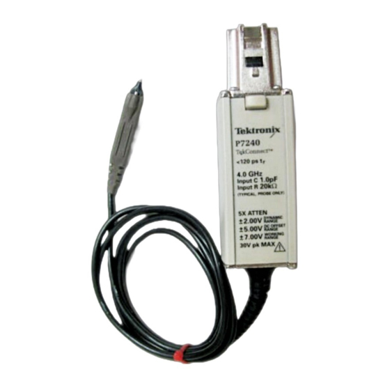
Product Description The Tektronix P7240 is a 4 GHz (probe only), 5X active FET probe. The P7240 has a low input capacitance (1 pF) and high input resistance (20 kΩ), which minimize circuit loading over a wide bandwidth range. The small profile and low-mass head of the P7240 make probing dense circuitry by hand fast and easy. -
Page 12: Installation
See Figure 2. To release the probe from the oscilloscope, grasp the compensation box, depress the latch button, and pull out the probe. Latch button Figure 2: Connecting and disconnecting the probe P7240 4 GHz 5X Active Probe User Manual... -
Page 13: Options
Product Description Options The following options are available when ordering the P7240 probe: H Option D1 - - Calibration Data H Option C3 - - 3 years Calibration Service H Option D3 - - 3 years Calibration Data (requires Option C3) - Page 14 Product Description P7240 4 GHz 5X Active Probe User Manual...
-
Page 15: Features And Accessories
Features and Accessories The P7240 is provided with several features and accessories designed to make probing and measurement a simpler task. To familiarize yourself with these items and their uses, refer to Table 1. Table 1: P7240 features and standard accessories... - Page 16 Features and Accessories Table 1: P7240 features and standard accessories (Cont.) Feature/Accessory Description Installing the push-in probe tip. Attach the push-in probe tip by aligning the tip into the probe tip socket and pushing the tip in until it is seated.
- Page 17 Features and Accessories Table 1: P7240 features and standard accessories (Cont.) Feature/Accessory Description Y-lead adapter (2 ea). Use the Y-lead adapter Y-lead to extend the physical reach of the probe and adapter ground when necessary. The Y-lead adapter accepts any of the probe tips or adapters, and can be pushed directly onto 0.025 inch square-...
- Page 18 Features and Accessories Table 1: P7240 features and standard accessories (Cont.) Feature/Accessory Description Customizable ground lead (5 ea) . This ground lead wire can be bent or cut shorter. NOTE: To ease insertion into the ground socket of the probe, cut the tip of this ground lead wire at a 30 to 60 degree angle.
- Page 19 Features and Accessories Table 1: P7240 features and standard accessories (Cont.) Feature/Accessory Description Low-inductance ground pogo pin (10 ea). Use the low-inductance ground pogo pin to substantially reduce ground lead inductance. Because the pogo pin simply touches the ground reference, you can easily move the probe to different points on the circuit under test.
- Page 20 Features and Accessories Table 1: P7240 features and standard accessories (Cont.) Feature/Accessory Description Antistatic wrist strap. When using the probe, always work at an antistatic work station and wear the antistatic wrist strap. Tektronix part number: 006-3415-04 Plastic accessory box. Use the plastic box to store the probe accessories when not in use.
- Page 21 Features and Accessories Table 2 lists the optional accessories you can order for your P7240 probe. Table 2: P7240 optional accessories Accessory Description SureFoot probe tip. The SureFoot tip is an integral probe tip and miniature guide that enables fault-free probing of fine-pitch SMD packages.
- Page 22 Use the Optional Applications Software CD that is shipped with oscilloscopes featuring the TekConnect interface. Alternatively, you can download the software from the Tektronix website, or order the CD using the part number below. Tektronix part number: 063-3376-XX P7240 4 GHz 5X Active Probe User Manual...
-
Page 23: Functional Check
PROBE COMPENSATION BNC connector on the oscilloscope. 5. Press AUTOSET, or adjust the oscilloscope to display a stable calibration waveform. (You may need to adjust the probe offset to display the waveform.) P7240 4 GHz 5X Active Probe User Manual... - Page 24 8. Set the oscilloscope volts/division to 500 mV. 9. Adjust the probe offset. The displayed waveform should vary between approximately +1.0 V and - - 1.0 V. P7240 4 GHz 5X Active Probe User Manual...
-
Page 25: Configuration
Configuration The P7240 provides the oscilloscope with the probe model number, serial number, and attenuation factor. When connected to an oscilloscope with a TekConnect interface, display readouts are corrected for the probe attenuation factor, the instrument input is set to 50 Ω, and the coupling is set to DC. The probe offset control is controlled by the oscilloscope. -
Page 26: Figure 4: Dynamic And Offset Limitations
Configuration NOTE. The P7240 has a ±5.0 V offset range. The linear operating range is ±2.0 V. See Figure 4. If cursors are used on a TekConnect interface oscilloscope, the zero reference will be at the probe offset voltage. Nonoperating range (+30 V maximum nondestructive input voltage ) +7.0 V... -
Page 27: Operating Basics
P7240 probe. Handling the Probe Exercise care when using and storing the P7240. The probe and cable are susceptible to damage caused by careless use. Always handle the probe using the compensation box and probe head, avoiding undue physical strain to the probe cable, such as kinking, excessive bending, or pulling. -
Page 28: Ground Lead Length
Ground Lead Inductance When you touch your probe tip to a circuit element, you are introducing a new resistance, capacitance, and inductance into the circuit. Refer to Figure 6 on page 19. P7240 4 GHz 5X Active Probe User Manual... -
Page 29: Figure 6: Ground Lead Equivalent Circuit
The low-inductance ground contacts described in Features and Accessories starting on page 5 can help you reduce the effects of ground lead inductance on your measurements. P7240 4 GHz 5X Active Probe User Manual... - Page 30 Operating Basics P7240 4 GHz 5X Active Probe User Manual...
-
Page 31: Helpful Hints
Attach a small piece of copper clad on top of the package and connect it to the package ground connection. Use the low-inductance ground lead provided with the P7240 to keep the ground lead length as short as possible. P7240 4 GHz 5X Active Probe User Manual... -
Page 32: Surefoot Grounding
Use a SureFoot adapter at the end of a short ground lead to connect directly to the package ground. This method is preferred over using an adjacent circuit ground because it is the shortest ground path possible. P7240 4 GHz 5X Active Probe User Manual... -
Page 33: Appendix A: Specifications
Appendix A: Specifications These specifications apply to a P7240 probe when used with a TDS7404 oscilloscope. The probe and oscilloscope must first be allowed to warm up for 20 minutes before measurements are taken. Specifications CAUTION. To prevent damage to the probe or circuit under test, do not apply voltages beyond the nondestructive input voltage range to the probe. -
Page 34: Figure 9: Typical Input Impedance And Phase Versus Frequency
10 K 0° - - 18° Phase - - 36° - - 54° - - 72° - - 90° 10 M 100 M Frequency Figure 9: Typical input impedance and phase versus frequency P7240 4 GHz 5X Active Probe User Manual... -
Page 35: Figure 10: Typical Bandwidth
31.8 mm (1.250 in) 57.2 mm (2.250 in) 7.6 mm (0.300 in) 43.8 mm (1.725 in) 63.5 mm (2.500 in) 91.5 mm (3.600 in) Figure 11: Probe head and compensation box dimensions P7240 4 GHz 5X Active Probe User Manual... - Page 36 Cycle 1 Assurance Level II for packaged products 0 to 20 lbs. Test 2 for Warehouse and Vehicle Stacking (Compression) is omitted. Tektronix standard 062-2858-00, Rev. B, Class 5. Altitude Operating: 15,000 ft. Nonoperating: 50,000 ft. P7240 4 GHz 5X Active Probe User Manual...
-
Page 37: Appendix B: User Service
Calibration If you need to do a performance verification or make internal adjustments to your probe, refer to the P7240 4 GHz Active Probe Service Manual, Tektronix part number 071-1056-XX. The manual is a printable pdf file, and is available on both the Tektronix website and the Optional Applications CD, Tektronix part number 063-3376-XX. -
Page 38: Preparation For Shipment
2. Put the probe into antistatic bag or wrap to protect it from dampness. 3. Place the probe into the box and stabilize it with light packing material. 4. Seal the carton with shipping tape. P7240 4 GHz 5X Active Probe User Manual... -
Page 39: Appendix C: Replaceable Parts
Appendix C: Replaceable Parts This section contains a list of replaceable parts for the P7240 probe. Use this list to identify and order replacement parts. Parts Ordering Information Replacement parts are available from or through your local Tektronix, Inc. service center or representative. -
Page 40: Using The Replaceable Parts List
Indented items are part of, and included with, the next higher indentation. Attaching parts must be purchased separately, unless otherwise specified. Abbreviations Abbreviations conform to American National Standards Institute (ANSI) standard Y1.1 P7240 4 GHz 5X Active Probe User Manual... - Page 41 Appendix C: Replaceable Parts P7240 4 GHz 5X Active Probe User Manual...
-
Page 42: Figure 13: P7240 Standard Accessories
Appendix C: Replaceable Parts P7240 4 GHz 5X Active Probe User Manual... - Page 43 Appendix C: Replaceable Parts P7240 4 GHz 5X Active Probe User Manual...
-
Page 44: Figure 14: P7240 Optional Accessories
Appendix C: Replaceable Parts P7240 4 GHz 5X Active Probe User Manual... - Page 45 Appendix C: Replaceable Parts P7240 4 GHz 5X Active Probe User Manual...
- Page 46 Appendix C: Replaceable Parts P7240 4 GHz 5X Active Probe User Manual...
Need help?
Do you have a question about the P7240 and is the answer not in the manual?
Questions and answers