Sign In
Upload
Manuals
Brands
Tektronix Manuals
Measuring Instruments
P7240
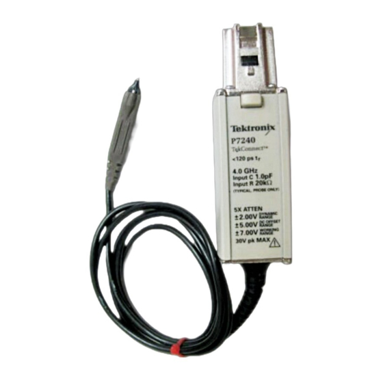
Tektronix P7240 Manuals
Manuals and User Guides for Tektronix P7240. We have
2
Tektronix P7240 manuals available for free PDF download: Technical Reference, User Manual
Tektronix P7240 Technical Reference (58 pages)
Brand:
Tektronix
| Category:
Measuring Instruments
| Size: 3 MB
Table of Contents
Table of Contents
8
General Safety Summary
11
Preface
14
Theory of Operation
16
Introduction
16
Figure 1: Adapters for the P7600 Series Probes
18
Figure 2: Probe Tip Selection Screen
19
Trimode Operation
21
Figure 3: Trimode Input Structure
22
Figure 4: Typical Trimode Probe Setup Screen
22
Operating Voltages
23
Figure 5: Probe Inputs
23
Figure 6: Operating Voltage Window
24
Figure 7: Dynamic Range Versus Linearity
25
Figure 8: Termination Voltage Operating Range
26
Figure 9: Probe Setup Screen
27
Input Impedance and Probe Loading
29
Figure 10: Trimode Probe Coaxial Input Model
29
Figure 11: P76TA Adapter Simplified Schematic
30
Figure 12: P76TA Adapter and P75PST Tip Equivalent Schematic
30
Scale Factor
31
Probing Techniques to Maximize Measurement Fidelity
32
Figure 13: Preventing Twist to the Coaxial Input Cables
32
Figure 14: P75PST and P75TLRST Trimode Solder Tips
33
Figure 15: Solder Ramp Installed
33
Figure 16: Typical Wire Length from Probe Tip to Circuit
35
Figure 17: P75TLRST Solder Tip with 0.010 In. of Tip Wire
36
Figure 18: P75TLRST Solder Tip with 0.050 In. of Tip Wire
36
Figure 19: P75TLRST Solder Tip with 0.100 In. of Tip Wire
37
Figure 20: P75TLRST Solder Tip with 0.200 In. of Tip Wire
37
Reference
38
Single-Ended Measurements Using a and B Modes
38
Table 1: Offset Ranges
38
Differential Measurements
39
Figure 21: Simplified Model of a Differential Amplifier
39
Figure 22: Typical CMRR
40
Figure 23: Typical Channel Isolation
41
Specifications
42
Warranted Characteristics
42
Table 2: Warranted Electrical Characteristics
42
Typical Characteristics
44
Table 3: Warranted Environmental Characteristics
44
Table 4: Typical Electrical Characteristics
44
Table 5: Typical Mechanical Characteristics
45
Figure 24: Typical Rise Time
46
Figure 25: Typical Frequency Response
46
Figure 26: Probe Body and Control Box Dimensions
47
Figure 27: P7600 Series Probe Adapter Dimensions
48
Figure 28: P75PST and P75TLRST Solder Tip Dimensions
48
Nominal Characteristics
49
Table 6: Nominal Electrical Characteristics
49
Table 7: Nominal Adapter Electrical Characteristics
49
User Service
50
Error Condition
50
Replaceable Parts
50
Table 8: Trimode Probes Replaceable Parts
50
Table 9: Required Equipment
50
Figure 29: Removing the Bullets
52
Figure 30: Installing the Bullets
53
Preparation for Shipment
56
Index
58
Advertisement
Tektronix P7240 User Manual (46 pages)
4 GHz 5X Active Probe
Brand:
Tektronix
| Category:
Measuring Instruments
| Size: 0 MB
Table of Contents
General Safety Summary
5
Table of Contents
7
Preface
9
Related Manuals
9
Contacting Tektronix
10
Figure 1: P7240 Probe Featuring the Tekconnect Interface
11
Product Description
11
Tekconnect Interface
11
Figure 2: Connecting and Disconnecting the Probe
12
Installation
12
Options
13
Features and Accessories
15
Figure 3: Probe Functional Check Connections
23
Functional Check
23
Configuration
25
Probe Offset
25
Figure 4: Dynamic and Offset Limitations
26
Operating Basics
27
Handling the Probe
27
Maximum Nondestructive Input Voltage
27
Input Linear Dynamic Range
27
Figure 5: Waveform Distortion from Ground Lead Length
28
Ground Lead Length
28
Ground Lead Inductance
28
Figure 6: Ground Lead Equivalent Circuit
29
Figure 7: Low-Inductance Grounding
31
Helpful Hints
31
Low-Inductance Grounding
31
Figure 8: Using a Surefoot Adapter for Grounding
32
Surefoot Grounding
32
Appendix A: Specifications
33
Specifications
33
Figure 9: Typical Input Impedance and Phase Versus Frequency
34
Figure 10: Typical Bandwidth
35
Figure 11: Probe Head and Compensation Box Dimensions
35
Appendix B: User Service
37
Inspection and Cleaning
37
Calibration
37
Replacement Parts
37
Preparation for Shipment
38
Appendix C: Replaceable Parts
39
Parts Ordering Information
39
Using the Replaceable Parts List
40
Figure 13: P7240 Standard Accessories
42
Figure 14: P7240 Optional Accessories
44
Advertisement
Related Products
Tektronix P7260
Tektronix TriMode P7700 Series
Tektronix P7350
Tektronix TriMode P7513
Tektronix TriMode P7520A
Tektronix TriMode P7516
Tektronix TriMode P7520
Tektronix PL-1391/U
Tektronix P6202A
Tektronix P6016
Tektronix Categories
Test Equipment
Measuring Instruments
Amplifier
Portable Generator
Printer
More Tektronix Manuals
Login
Sign In
OR
Sign in with Facebook
Sign in with Google
Upload manual
Upload from disk
Upload from URL