
Related Manuals for Icom IC-V3MR


Summary of Contents for Icom IC-V3MR
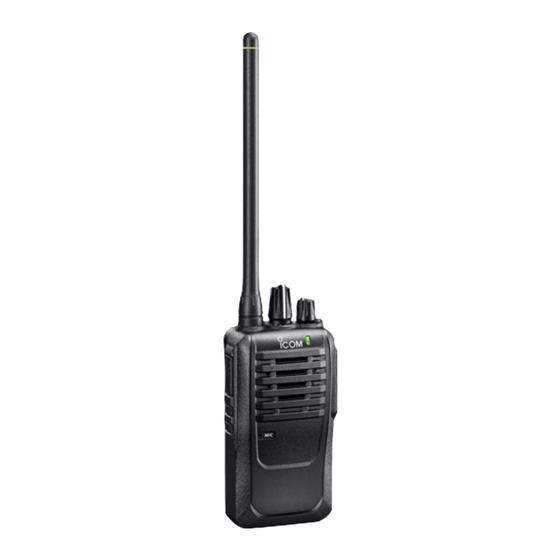
- Page 1 INSTRUCTION MANUAL INTRODUCTION ACCESSORIES VHF TRANSCEIVER PANEL DESCRIPTION |V3MR BASIC OPERATION ADVANCED OPERATION BATTERY CHARGING OPTIONS...
- Page 2 INTRODUCTION Thank you for choosing this Icom product. This product was designed and built with Icom’s state of the art technology and craftsmanship. With proper care, this product should provide you with years of trouble-free operation. IMPORTANT FIRST, CAREFULLY READ INSTRUCTIONS that is provided with the transceiver.
- Page 3 This could cause an explosion and +60°C (+140°F), or in areas subject to direct sunlight, death. such as the dashboard. R WARNING! NEVER use or charge Icom battery DO NOT push PTT unless you actually intend to packs with non-Icom transceivers or non-Icom transmit.
- Page 4 2019), IEEE Standard for Safety Levels with away from the body when transmitting, and only Respect to Human Exposure to Radio Frequency use the Icom belt-clip listed in “OPTIONS” on this Electromagnetic Fields, 0 Hz to 300 GHz. instruction manual when attaching the radio to your belt, or other place, to ensure FCC RF exposure •...
- Page 5 Moni (Monitor) button was • Consult the dealer or an experienced radio/TV disabled. technician for help. CAUTION: Changes or modifications to this transceiver, not expressly approved by Icom Inc., could void your authority to operate this transceiver under FCC regulations.
- Page 6 Section ACCESSORIES Supplied accessories �����������������������������������������������������������������������1-2 Belt clip ���������������������������������������������������������������������������������������������1-2 Flexible antenna �������������������������������������������������������������������������������1-2 Battery pack �������������������������������������������������������������������������������������1-3 Jack cover ����������������������������������������������������������������������������������������1-3...
- Page 7 ACCESSORIES Supplied accessories Belt clip Attaching: Battery pack Battery charger Belt clip (BP-298) (BC-240) (MB-124) 1� Remove the battery pack from the transceiver if it is attached� 2� Slide the belt clip in the direction of the arrow until the belt clip is locked and makes a ‘click’ sound� Belt clip Battery pack Power adapter...
- Page 8 ACCESSORIES Battery pack Jack cover Attaching: Attach the jack cover when optional equipment is not 1� Insert the battery pack in the direction of the arrow used� (1), and then close it� 2� Hook the latch until it makes a ‘click’ sound (2)� Attaching: 1�...
- Page 9 Section PANEL DESCRIPTION Front, top and side panels ����������������������������������������������������������������2-2 D Status indicator ����������������������������������������������������������������������������������������2-2 D Speaker microphone jack �������������������������������������������������������������������������2-2 D About the Software Key functions ������������������������������������������������������������2-2 Status indicator ���������������������������������������������������������������������������������2-3 Assignable Software Key functions ��������������������������������������������������2-4...
- Page 10 PANEL DESCRIPTION Front, top and side panels DStatus indicator [Rotary • Lights red: Transmitting� Antenna Selector] • Lights green: Receiving or squelch is open� connector • Lights or blinks orange: A matching signal is [VOL] received, depending on the presetting� Status L Refer to the Status indicator section�...
- Page 11 PANEL DESCRIPTION Status indicator The Status indicator indicates the status of various parameters of the transceiver, as described below� (Reference: R=Red, G=Green, O=Orange) • TX: Lights while transmitting� • RX: Lights green while receiving a signal� • Call LED (ON): Blinks about once every second when the specified signal is received�...
- Page 12 PANEL DESCRIPTION Assignable Software Key functions Disable High/Low Set to disable the key� Push to select the transmit output power level temporarily, or permanently, depending on the NOTE: This key function is assignable to only presetting� [Ext� Emer]� DTMF Autodial Push to transmit a DTMF code�...
-
Page 13: Table Of Contents
Section BASIC OPERATION Turning ON the transceiver ��������������������������������������������������������������3-2 D Adjusting the audio level ��������������������������������������������������������������������������3-2 Selecting a channel ��������������������������������������������������������������������������3-2 D Selecting an operating channel ����������������������������������������������������������������3-2 D Default frequencies chart �������������������������������������������������������������������������3-2 D Selecting the Priority A or B channel ��������������������������������������������������������3-2 D Rewriting the Priority A or B channel ��������������������������������������������������������3-2 Call procedure ����������������������������������������������������������������������������������3-3 Receiving and transmitting ���������������������������������������������������������������3-4 D Receiving �������������������������������������������������������������������������������������������������3-4... -
Page 14: Section 3 Basic Operation
BASIC OPERATION Turning ON the transceiver Selecting a channel DSelecting an operating channel NOTE: Before using the transceiver for the first time, the battery pack must be fully charged for optimum z Rotate [Rotary Selector] to select an operating life and operation� See “BATTERY CHARGING�” channel�... -
Page 15: Call Procedure
BASIC OPERATION Call procedure When your system uses tone signaling (except 1� Select a channel according to your system CTCSS and DTCS), a call procedure may be operator’s instructions� necessary prior to voice transmission� The tone L This may not be necessary, depending on the presetting�... -
Page 16: Receiving And Transmitting
BASIC OPERATION Receiving and transmitting DTransmitting notes CAUTION: DO NOT transmit without an antenna� Transmit inhibit function The transceiver has several inhibit functions which DReceiving restrict transmission under the following conditions: 1� Rotate [Rotary Selector] to select a channel� • The channel is busy� 2�... -
Page 17: Dtransmitting A Dtmf Code (Autodial)
BASIC OPERATION Setting the microphone gain Receiving and transmitting DTransmitting a DTMF code (Autodial) The higher value makes the microphone more sensitive to your voice� You can quickly send DTMF tones that have been pre- entered into the transceiver� 1� Rotate [VOL] to turn OFF the transceiver� 2�... -
Page 18: Setting The Squelch Level
BASIC OPERATION Setting the squelch level Selecting the output power level The squelch circuit mutes the received audio signal, If the transceiver has [High/Low] assigned to it, depending on the signal strength� the transmit output power level can be selected, depending on the presetting�... - Page 19 Section ADVANCED OPERATION Emergency Call ��������������������������������������������������������������������������������4-2 Lone Worker Emergency Call ����������������������������������������������������������4-3 MDC 1200 system operation ������������������������������������������������������������4-3 D Transmitting an Emergency Call ��������������������������������������������������������������4-3...
- Page 20 ADVANCED OPERATION Emergency Call When the Emergency function is turned ON, a IMPORTANT: It is recommended that the dealer countdown starts� The transceiver counts down during set up an Emergency channel to provide reliable the Reminder Timer set time� Emergency call operation� If no Emergency channel is specified, the Emergency NOTE: Depending on the presetting, the following call is made on the previously selected channel�...
- Page 21 ADVANCED OPERATION Lone Worker Emergency Call MDC 1200 system operation When the Lone Worker function is turned ON, and The MDC 1200 signaling system enhances your no operation occurs for the specified period of time, transceiver’s capabilities� It allows PTT ID and the Emergency function is automatically turned ON, Emergency signaling�...
- Page 22 Section BATTERY CHARGING Battery caution ���������������������������������������������������������������������������������5-2 Charging caution ������������������������������������������������������������������������������5-3 Battery chargers �������������������������������������������������������������������������������5-4 D Rapid charging with the BC-240 ��������������������������������������������������������������5-4 D About the BC-240 �������������������������������������������������������������������������������������5-4 D Rapid charging with the BC-214N ������������������������������������������������������������5-5...
-
Page 23: Section 5 Battery Charging
R DANGER! NEVER solder the battery terminals, or or deformed� If any of these conditions occur, contact NEVER modify the battery pack� This may cause heat your Icom dealer or distributor� generation, and the battery may burst, emit smoke or catch fire�... -
Page 24: Charging Caution
CAUTION: DO NOT charge the battery pack outside of the specified temperature range: 10°C ~ 40°C (50°F ~ 104°F)� Icom recommends charging the pack at 20°C (68°F)� The pack may heat up or rupture if charged out of the specified temperature range�... -
Page 25: Battery Chargers
BATTERY CHARGING Battery chargers DRapid charging with the BC-240 DAbout the BC-240 You can rapidly charge a Li-ion battery pack with the Turn the Extend Battery Life function ON or OFF� The BC-240� battery charger has a function switch on the bottom panel�... -
Page 26: Drapid Charging With The Bc-214N
BATTERY CHARGING Battery chargers DRapid charging with the BC-214N You can rapidly and simultaneously charge up to 6 battery packs with the optional BC-214N (with AD-139 charger adapters installed)� Charging time for the BP-298: Approximately 3 hours Additionally needed item (purchase separately): The BC-157S ac adapter Turn OFF Battery pack... - Page 27 Section OPTIONS Options ���������������������������������������������������������������������������������������������6-2 D Battery pack ���������������������������������������������������������������������������������������������6-2 D Chargers ��������������������������������������������������������������������������������������������������6-2 D DC cables �������������������������������������������������������������������������������������������������6-2 D Antenna ����������������������������������������������������������������������������������������������������6-2 D Others ������������������������������������������������������������������������������������������������������6-2 VOX function ������������������������������������������������������������������������������������6-3 D Connecting the optional unit ���������������������������������������������������������������������6-3 D Turning the VOX function ON or OFF ������������������������������������������������������6-4 D Setting the VOX gain ��������������������������������������������������������������������������������6-4...
- Page 28 Set modes DAntenna contents� Ask your dealer for details� • FA-SC28V vhf antenna You can download the CS-V3MR programming software from the Icom website� 148 ~ 162 MHz (https://www�icomjapan�com/support/) • OPC-474 programming cable For transceiver-to-transceiver programming�...
- Page 29 OPTIONS VOX function The transceiver has a VOX function, which allows you hands-free operation� An optional HS-94, HS-95 or HS-97 headset and the VS-4LA ptt switch cable, or the OPC-2004 or OPC-2004LA adapter cable are also required for operation� What is VOX? The VOX (voice operated transmission) function starts transmission when you speak into the microphone, without pushing [PTT], and then...
- Page 30 OPTIONS VOX function DTurning the VOX function ON or OFF DSetting the VOX gain The VOX function can be turned ON or OFF� The VOX The higher value makes the VOX function more function automatically switches between receive and sensitive to your voice� transmit during voice operation�...
- Page 31 A7647-2US 1-1-32 Kamiminami, Hirano-ku, Osaka 547-0003, Japan © 2021 Icom Inc. Sep. 2021...
Need help?
Do you have a question about the IC-V3MR and is the answer not in the manual?
Questions and answers