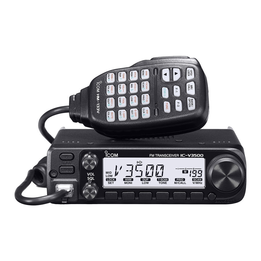
Icom IC-V3500 - 2M VHF FM Mobile Transceiver Manual
- Advanced manual (89 pages)
Advertisement
![]()
Important
SAVE THESE INSTRUCTIONS— This instruction manual contains basic operating instructions for the IC-V3500. For advanced operating instructions, see the ADVANCED MANUAL on the Icom website.
The Advanced manual can be found at the following internet address: https://www.icomjapan.com/support/
This instruction sheet includes some functions that are usable only when they are preset by your dealer. The transceiver may have other functions and operations that are not described in this instruction sheet. Ask your dealer for details.
Explicit definitions
| WORD | DEFINITION |
 | Personal death, serious injury or an explosion may occur. |
 | Personal injury, fi re hazard or electric shock may occur. |
 | Equipment damage may occur. |
| NOTE | If disregarded, inconvenience only. No risk of personal injury, fi re or electric shock. |
Icom is not responsible for the destruction, damage to, or performance of any Icom or non-Icom equipment, if the malfunction is because of:
- Force majeure, including, but not limited to, fi res, earthquakes, storms, fl oods, lightning, other natural disasters, disturbances, riots, war, or radioactive contamination.
- The use of Icom transceivers with any equipment that is not manufactured or approved by Icom.
Supplied accessories
NOTE: Some accessories may not be supplied, or the shape may diff er, depending on the transceiver version.

Thank you for choosing this Icom product.
READ ALL INSTRUCTIONS carefully and completely before using this product.
Precautions

HIGH RF VOLTAGE! NEVER touch an antenna or antenna connector while transmitting. This could cause an electrical shock or burn.
NEVER operate the transceiver near unshielded electrical blasting caps or in an explosive atmosphere. This could cause an explosion and death.
NEVER place the transceiver where airbag deployment may be obstructed during mobile operations.
RF EXPOSURE! This transceiver emits Radio Frequency (RF) energy. Extreme caution should be observed when operating this transceiver. If you have any questions regarding RF exposure and safety standards, please refer to the Federal Communications Commission Offi ce of Engineering and Technology's report on Evaluating Compliance with FCC Guidelines for Human Radio Frequency Electromagnetic Fields (OET Bulletin 65).
NEVER connect the transceiver to an AC outlet.
This may pose a fire hazard and/or result in an electric shock.
NEVER operate the transceiver during a lightning storm. It may result in an electric shock, cause a fire or damage the transceiver. Always disconnect the power source and antenna before a storm.
NEVER cut the DC power cable between the DC plug and fuse holder. If an incorrect connection is made after cutting, the transceiver may be damaged.
NEVER connect the transceiver to a power source of more than 16 V DC, such as a 24 V battery. This could damage the transceiver.
NEVER operate or touch the transceiver with wet hands. This could cause an electric shock or damage the transceiver.
NEVER place the transceiver where the vehicle's normal operation may be hindered or where it could cause bodily injury.
NEVER let metal, wire, or other objects contact the transceiver inside or make incorrect contact with connectors on the rear panel. This could cause an electric shock or damage the transceiver.
NEVER operate the equipment if you notice an abnormal odor, sound, or smoke. Immediately turn OFF the power and the DC power cable. Contact your Icom dealer or distributor for advice.
DO NOT operate the transceiver while driving a vehicle. Safe driving requires your full attention—anything less may result in an accident.
DO NOT reverse the DC power cable polarity.
This could damage the transceiver.
DO NOT expose the transceiver to rain, snow, or any liquids. They could damage the transceiver.
DO NOT operate the transceiver without running the vehicle's engine. The vehicle's battery will quickly run out when the transceiver is used while the vehicle's engine is OFF.
DO NOT install or place the transceiver in a place without adequate ventilation or block any cooling vents on the top, rear, sides, or bottom of the transceiver. Heat dissipation may be reduced and damage the transceiver.
DO NOT use harsh solvents such as Benzine or alcohol when cleaning. This could damage the equipment surfaces. If the surface becomes dusty or dirty, wipe it clean with a soft, dry cloth.
DO NOT use or leave the transceiver in areas with temperatures below −10°C or above +60°C, or in areas exposed to direct sunlight, such as the dashboard.
DO NOT use or leave the transceiver in excessively dusty environments. This could damage the transceiver.
DO NOT use the non-specified microphone. Other microphones have diff erent pin assignments and may damage the transceiver.
NEVER place the transceiver in an insecure place to avoid inadvertent use by unauthorized persons.
DO NOT push PTT unless you actually intend to transmit.
DO NOT place the transceiver where hot or cold air blows directly onto it, during mobile operation.
NOTE: During maritime mobile operation, keep the transceiver and microphone as far away as possible from the magnetic navigation compass to prevent erroneous indications.
FCC information
This equipment has been tested and found to comply with the limits for a Class B digital device, pursuant to part 15 of the FCC Rules. These limits are designed to provide reasonable protection against harmful interference in a residential installation. This equipment generates, uses, and can radiate radio frequency energy and, if not installed and used in accordance with the instructions, may cause harmful interference to radio communications. However, there is no guarantee that interference will not occur in a particular installation. If this equipment does cause harmful interference to radio or television reception, which can be determined by turning the equipment off and on, the user is encouraged to try to correct the interference by several of the following measures:
- Reorient or relocate the receiving antenna.
- Increase the separation between the equipment and receiver.
- Connect the equipment into an outlet on a circuit diff erent from that to which the receiver is connected.
- Consult the dealer or an experienced radio/TV technician for help.
Changes or modifications to this transceiver, not expressly approved by Icom Inc., could void your authority to operate this transceiver under FCC regulations.
This device complies with part 15 of the FCC Rules. Operation is subject to the condition that this device does not cause harmful interference.
Canada information
This device complies with Industry Canada license-exempt RSS standard(s). Operation is subject to the following two conditions:
- this device may not cause interference, and
- this device must accept any interference, including interference that may cause undesired operation of the device.
Panel description
NOTE: The Marine and WX Channel mode may not be used, depending on the transceiver version.
Front panel

- POWER KEY [
![]() ]
]
Hold down for 1 second to turn the transceiver ON or OFF. - MEMORY WRITE KEY [S.MW MW]
 ]
] - Push to enter the Memory Write mode.
- Hold down for 1 second to set the selected Memory channel.
![information]() Continue to hold down the key to automatically increment the Memory channels.
Continue to hold down the key to automatically increment the Memory channels.
- MICROPHONE CONNECTOR
Connects to the supplied microphone. - VOLUME CONTROL [VOL]
Rotate to adjust the audio level. - SQUELCH CONTROL [SQL]
Rotate to adjust the squelch level.
![information]() The S-meter squelch or attenuator squelch is activated when rotating [SQL] right from the 12 o'clock position.
The S-meter squelch or attenuator squelch is activated when rotating [SQL] right from the 12 o'clock position. - SET LOCK KEY [SET LOCK]
- Push to enter to the Set mode.
- Hold down for 1 second to turn the Lock function ON or OFF.
- MONITOR CHANNEL NAME PA KEY [MONI ANM PA]
- Push to turn the monitor function ON or OFF.
- In the Memory or Call Channel mode, hold down for 1 second to turn the channel name or number ON or OFF.
- In the Marine Channel mode, hold down for 1 second to turn the Public Address function ON or OFF.
- OUTPUT POWER DUPLEX KEY [LOW DUP]
- Push to select the output power.
- Hold down for 1 second to select the minus Duplex, plus Duplex, or Simplex mode.
- TONE- TONE SCAN KEY [TONE T-SCAN]
- Push to select the Tone function.
- Hold down for 1 second to start a Tone scan.
- MEMORY/CALL PRIORITY KEY [M/CALL PRIO]
- Push to select the Memory, Call, Marine, or WX Channel mode.
- Hold down for 1 second to start a Priority Watch.
- VFO/MHz TUNING SCAN KEY [V/MHz SCAN]
- Push to select the VFO mode.
![information]() In the VFO mode, push to select the 10 MHz or 1 MHz tuning step.
In the VFO mode, push to select the 10 MHz or 1 MHz tuning step. - Hold down for 1 second to start a scan.
![information]() Push to cancel a scan.
Push to cancel a scan.
- BANK OPTION KEY [BANK OPT]
- In the Memory mode, push to select a memory bank.
- Hold down for 1 second to enter the Option Set mode.
- In the Marine Channel mode, hold down for 1 second to enter the Marine Set mode.
![information]() You can assign the Emergency Alert function or the Temporary Volume function to this key. See the Advanced manual for details.
You can assign the Emergency Alert function or the Temporary Volume function to this key. See the Advanced manual for details.
- TUNING DIAL [DIAL]
- Select the operating frequency or Memory channel.
- Select an item in the Set mode.
- Change the scanning direction.
Microphone connector information

- +8 V DC output (Maximum 35 mA)
- Channel up/down
- 8 V control IN
- PTT
- GND (microphone ground)
- MIC (microphone input)
- GND
- Data IN
Rear panel

- ANTENNA CONNECTOR [ANT]
Connects to a 50 Ω antenna through a 50 Ω PL-259 coaxial cable. - POWER RECEPTACLE [DC13.8V]
Connect a 13.8 V DC ±15% power source with the supplied DC power cable.
NOTE: DO NOT use a cigarette lighter socket as a power source when operating in a vehicle. The plug may cause voltage drops, and ignition noise may be superimposed onto the transmit or receive audio. - SPEAKER JACK [SP]
Connects to a 4 Ω speaker.
![information]() Audio output power is more than 3.5 W.
Audio output power is more than 3.5 W.
Function display

- FREQUENCY READOUT
Displays the operating frequency, channel name, Set mode contents, and so on.
- The frequency decimal point blinks during a scan.
- In the DTMF Memory mode, "d" is displayed in the 100 MHz digits.
- TRANSMIT ICON
- Displayed while transmitting.
- Blinks while transmitting when the One-Touch PTT function is ON.
- AUDIO MUTE ICON
Displayed when the Audio Mute function is ON. - NARROW MODE ICON
Displayed when "Narrow" is selected in the Wide/Narrow setting. - OUTPUT POWER ICONS
Displays the selected output power level.
![information]() If no output power icon is displayed, the level is set to "High."
If no output power icon is displayed, the level is set to "High." - KEY ICONS
Displays the functions of the keys directly below the function display. - SKIP ICON
Displayed when the selected Memory channel is set as a Skip channel. - Memory channel NUMBER READOUT
- Displays the selected Memory channel number.
- A "C" is displayed when the Call channel is selected.
NOTE: When the VFO mode is selected from the Call Channel mode, a small "c" is displayed instead of the Memory channel number.
- MEMORY ICON
Displayed when the Memory mode is selected. - S/RF INDICATOR
- Displays the relative signal strength while receiving signals.
- Displays the output power level while transmitting.
- BUSY ICON
- Displayed while receiving a signal or the squelch is open.
- Blinks when the Monitor function is ON.
- S-METER SQUELCH ICON
Displayed when the S-meter Squelch function is ON. - SQUELCH ATTENUATOR ICON
Displayed when the Squelch Attenuator function is ON. - PRIORITY WATCH ICON
Displayed during a Priority Watch. - AUTO POWER OFF ICON
Displayed when the Auto Power OFF function is ON. - TONE ICONS
Displayed when the Tone function is ON.
![information]() Push [TONE T-SCAN] to select the tone function.
Push [TONE T-SCAN] to select the tone function.
 | Subaudible tone encoder (TX only) |
 and and  | CTCSS Pocket Beep function |
| | CTCSS Squelch function |
and  | DTCS encoder (only TX) |
| and | DTCS Pocket Beep function |
| | DTCS Squelch function |
| and -R | Reverse CTCSS Squelch function |
| and -R | Reverse DTCS Squelch function |
- DUPLEX ICONS
- A "+" is displayed when in the plus Duplex mode.
- A "–" is displayed when in the minus Duplex mode.
- FOGHORN ICON
Displayed when the Foghorn function is ON. - LOCK ICON
Displayed when the Lock function is ON.
Microphone
NOTE: The supplied microphone is diff erent, depending on the transceiver version.
HM-133V

- PTT SWITCH
- Hold down to transmit, release to receive.
- Push to switch between transmission and reception when the One-Touch PTT function is ON.
- UP/DOWN KEYS [▲] or [▼]
- Push to select the operating frequency, Memory channel, mode setting, and so on.
- Hold down either key for 1 second to start scanning.
![information]() The scanning direction follows the direction of the key's arrow.
The scanning direction follows the direction of the key's arrow.
- ACTIVITY INDICATOR
- Lights red when any key other than [FUNC] or [DTMF-S] is pushed, or while transmitting.
- Lights orange when the Microphone Keypad Lock function is ON.
- Lights green when the One-Touch PTT function is ON.
- KEYPAD
Push the keys to activate various functions. - FUNCTION INDICATOR
- Lights orange when [FUNC] is activated—indicating the secondary function of keys can be used.
- Lights green when [DTMF-S] is activated—DTMF signals can be transmitted using the keypad.
- FUNCTION KEY [FUNC]
Push this key and then push the keypad to turn the secondary function ON or OFF. - DTMF MEMORY SELECT KEY [DTMF-S]
Push to turn ON the DTMF direct selection.
![information]() See the table below for details.
See the table below for details. - FUNCTION KEYS [F-1] and [F-2]
Push to activate the assigned functions. - BANK/OPTION KEY [BANK/OPTION]
- In the Memory mode, push to select the memory bank option.
- In the Marine Channel mode, hold down for 1 second to select the Marine Set mode.
- In the Marine Set mode, push to select the next item.
- Hold down for 1 second to select the Option Set mode.
![information]() When the Emergency Alert function or the Temporary Volume function is assigned, each function is turned ON.
When the Emergency Alert function or the Temporary Volume function is assigned, each function is turned ON.
- MEMORY/CALL KEY [MR/CALL]
- Push to select the Memory mode.
- Hold down for 1 second to select the Call channel.
- In the Marine Set mode, push to select the previous item.
- VFO/LOCK KEY [VFO/LOCK]
- Push to select the VFO mode.
- Hold down for 1 second to turn the Lock function ON or OFF.
HM-133V Keypad
| KEY | FUNCTION | SECONDARY FUNCTION ( [FUNC]+key) |
 [MONI 1 ANM] | Opens or closes the squelch. | In the Memory mode, turns the channel names or number display ON or OFF. |
 [SCAN 2 T-SCAN] | Starts or stops scanning. | Starts and stops a Tone scan. |
 [PRIO 3 PTT-M] | Starts or stops a Priority Watch. | Turns the One-Touch PTT function ON or OFF. i See the Advanced manual for details. |
 [HIGH 4 DTCS] | Selects the high output power. | Turns ON the DTCS Squelch function. |
 [MID 5 DTCS  ] ] | Selects the middle output power. | Turns ON the DTCS Pocket Beep function. |
 [LOW 6 DTMF] | Selects the low output power. | Turns ON the DTMF memory encoder. |
 [DUP- 7 TONE] | Selects the minus Duplex mode. | Turns ON the subaudible tone encoder. |
 [DUP+ 8 TSQL  ] ] | Selects the plus Duplex mode. | Turns ON the CTCSS Pocket Beep function. |
 [SIMP 9 TSQL] | Selects the Simplex mode. | Turns ON the Tone Squelch function. |
 [VOL▲ 0 TONE-2] | Turns up the audio level. | Sends a 1750 Hz tone while holding down. |
 [CLR A MW] |
|
|
 [SET B D-OFF] |
| Turns OFF the DTMF Memory mode. |
 [ENT C T-OFF] |
| Turns OFF the DTCS/Tone squelch function, DTCS/CTCSS pocket beep function, or subaudible tone encoder. |
 [SQL▲ D MUTE] | Turns up the squelch level. | Turn the Audio Mute function ON or OFF.
|
 [VOL▼ TONE-1] [VOL▼ TONE-1] | Turns down the audio level. | Sends a 1750 Hz tone for 1 second. |
 [SQL▼ # 16KEY-L] [SQL▼ # 16KEY-L] | Turns down the squelch level. | Turn the Microphone Keypad Lock function ON or OFF.
Other keys and all keys on the transceiver can be used.
|
 ], and [#] keys) are locked.
NOTE: After pushing [DTMF-S], transmits the appropriate DTMF code. When the DTMF memory encoder is turned ON, push [A] to [D], [![]() ], [#], or [0] to [9] to transmit the appropriate DTMF memory contents.
], [#], or [0] to [9] to transmit the appropriate DTMF memory contents.
 When the audio level or the squelch level is changed from the HM-133V, the level will be displayed in the Memory channel number readout and the S/RF indicator. See the Advanced manual for details.
The output level cannot be changed from the HM-133V while transmitting.
HM-154

- PTT SWITCH
Hold down to transmit, release to receive. - UP/DOWN LOCK SWITCH
Slide to lock or unlock the UP/DOWN keys. - UP/DOWN KEYS [UP]/[DN]
- Push to change the operating frequency, Memory channel, Set mode setting, and so on.
- Hold down either key for 1 second to start scanning.
![information]() The scanning direction follows the direction of the key's arrow.
The scanning direction follows the direction of the key's arrow.
Basic operation

Transmission is inhibited in the Marine Channel mode.

Turning the transceiver ON/OFF
- Hold down [
![]() ] for 1 second to turn the transceiver ON or OFF.
] for 1 second to turn the transceiver ON or OFF.
 ] for 1 second to turn the transceiver ON or OFF.
VFO mode selection
The IC-V3500 has two basic operating modes, the VFO mode and the Memory mode.
- Push [V/MHz SCAN] to select the VFO mode.
![information]() Push [M/CALL PRIO] several times to select the Memory, Call, Marine, or WX Channel mode.
Push [M/CALL PRIO] several times to select the Memory, Call, Marine, or WX Channel mode.
Setting a frequency
- Push [V/MHz SCAN] to select the VFO mode.
- Rotate [DIAL] to set the frequency.
- The frequency changes according to the selected tuning step.
![information]() Push [V/MHz SCAN] several times to change the frequency step between 10 MHz and 1 MHz.
Push [V/MHz SCAN] several times to change the frequency step between 10 MHz and 1 MHz.
Tuning step selection
The selected tuning step is applied to the scan.
Option (kHz):
5.0, 6.25, 10.0, 12.5, 15.0, 20.0, 25.0, 30.0, 50.0
NOTE: For convenience, select the tuning step that matches the frequency intervals of the repeaters in your area.
- Push [V/MHz SCAN] to select the VFO mode.
- Push [SET LOCK] to enter the Set mode.
- Push [SET LOCK] or [MONI ANM PA] several times, until "TS" is displayed.
- Rotate [DIAL] to select the tuning step.
- Push any key other than [SET LOCK] or [MONI ANM PA] to save the entry and exit the Set mode.
Call channel selection
- Push [M/CALL PRIO] several times to select the Call channel.
- A "C" is displayed instead of a Memory channel number.
![information]() Push [M/CALL PRIO] more to select the Memory, Call, Marine, or WX Channel mode, or push [V/MHz SCAN] to select the VFO mode.
Push [M/CALL PRIO] more to select the Memory, Call, Marine, or WX Channel mode, or push [V/MHz SCAN] to select the VFO mode.
Receiving
- Hold down [
![]() ] for 1 second to turn ON the transceiver.
] for 1 second to turn ON the transceiver. - Rotate [VOL] to adjust the audio level.
![information]() Push [MONI ANM PA] to open the squelch, and then rotate [VOL] to adjust the audio level.
Push [MONI ANM PA] to open the squelch, and then rotate [VOL] to adjust the audio level. - Adjust the squelch level, as described below.
![information]() First, rotate [SQL] fully counterclockwise, and then rotate [SQL] clockwise until the noise just disappears.
First, rotate [SQL] fully counterclockwise, and then rotate [SQL] clockwise until the noise just disappears. - Set the operating frequency.
- When receiving a signal, the squelch opens, and audio can be heard.
 ] for 1 second to turn ON the transceiver.
 "BUSY" is displayed, and the S/RF indicator shows the relative strength of the received signal.
Transmitting
DO NOT transmit without an antenna.
NOTE: To prevent interference, listen to the channel before transmitting by opening the squelch. To open the squelch, rotate [DIAL] counterclockwise or push [SQL▼] on the microphone.
- Set the operating frequency.
- Adjust the output power if desired. See the Selecting output power section of this sheet.
- Hold down [PTT] to transmit.
- "
![]() " is displayed while transmitting.
" is displayed while transmitting.
![information]() The S/RF indicator shows the output power level.
The S/RF indicator shows the output power level.
![information]() The One-Touch PTT function can be used.
The One-Touch PTT function can be used.
 " is displayed while transmitting.
- Speak into the microphone at your normal voice level.
![information]() DO NOT hold the microphone too close to your mouth, or speak too loudly. This may distort the signal.
DO NOT hold the microphone too close to your mouth, or speak too loudly. This may distort the signal. - Release [PTT] to receive.
NOTE: When the TX Inhibit is set to "Inhibit," you cannot transmit. (Set in the CS-V3500 PROGRAMMING SOFTWARE.)
IMPORTANT for 65 W transmission:
The IC-V3500 has a built-in current detector circuit that protects the power amplifi er from excessive current fl ow. When excessive current fl ow is detected, the circuit automatically reduces the transmit output power to approximately 25 Watts.
The IC-V3500 has a thermal detector circuit too, which protects the power amplifi er from excessive heat. The circuit automatically reduces the transmit output power to approximately 10 to 20 Watts as the temperature increases.
Lock function
Activate to prevent accidental channel changes and unnecessary function access.
- Hold down [SET LOCK] for 1 second to turn the Lock function ON or OFF.
![information]() When the function is ON, "
When the function is ON, "![]() " is displayed.
" is displayed.
![information]() [PTT], [MONI ANM PA], [VOL], and [SQL] can be used, even when the function is ON.
[PTT], [MONI ANM PA], [VOL], and [SQL] can be used, even when the function is ON.
![information]() 1750 Hz tone, DTMF, Tones or DTMF Memory contents can be transmitted from the HM-133V.
1750 Hz tone, DTMF, Tones or DTMF Memory contents can be transmitted from the HM-133V.
 " is displayed.
Monitor function
This function is used to listen to weak signals, or to manually open the squelch. You can use it without disturbing the squelch setting, even when the Mute functions such as the Tone squelch are in use.
- Push [MONI ANM PA] to turn the Monitor function ON or OFF.
![information]() When the function is ON, "BUSY" blinks.
When the function is ON, "BUSY" blinks.
Squelch attenuator

The transceiver has an RF attenuator related to the squelch level setting. Approximately 20 dB of attenuation is obtained at the maximum setting.
Turn ON the Squelch Attenuator function:
- Hold down [
![]() ] for 1 second to turn OFF the transceiver.
] for 1 second to turn OFF the transceiver. - While holding down [SET LOCK], hold down [
![]() ] for 1 second to turn ON the transceiver and enter the Initial Set mode.
] for 1 second to turn ON the transceiver and enter the Initial Set mode. - Push [SET LOCK] or [MONI ANM PA] several times to select the "SQL" item.
- Rotate [DIAL] to select "AT" (Attenuator).
- Push [ ] to save and exit the Initial Set mode.
- Rotate [SQL] clockwise past the 12 o'clock position to turn ON the Squelch Attenuator function.
The attenuation level can be adjusted to approximately 20 dB between the 12 o'clock and fully clockwise positions.
When setting the squelch from the microphone, a level greater than '17' activates the attenuator.
NOTE: When using the Monitor function
The Squelch Attenuator function works even when the Monitor function is ON. It is recommended to set [SQL] between 10 and 12 o'clock (7 to 17 level when set using the HM-133V).
S-meter Squelch
The S-meter Squelch function disables the audio output from the speaker or headphones when the received signal is weaker than the specifi ed S-meter squelch level.
Turn ON the S-meter Squelch function:
- Hold down [
![]() ] for 1 second to turn OFF the transceiver.
] for 1 second to turn OFF the transceiver. - While holding down [SET LOCK], hold down [
![]() ] for 1 second to turn ON the transceiver and enter the Initial Set mode.
] for 1 second to turn ON the transceiver and enter the Initial Set mode. - Push [SET LOCK] or [MONI ANM PA] several times to select the "SQL" item.
- Rotate [DIAL] to select "SS" (S-meter squelch).
- Push [
![]() ] to exit the Initial Set mode.
] to exit the Initial Set mode. - Rotate [SQL] clockwise past the 12 o'clock position to turn ON the S-meter Squelch function.
Selecting output power
Set the output power level to suit your operating requirements. Lower output power during short-distance communications may reduce the possibility of interference to other stations and reduce the current consumption.
- Push [LOW DUP].
- The output power level is changed and the selected level is displayed.
If no output power icon is displayed, the level is set to "High."
The level can be changed even while transmitting.
Scan
Preparation
Set the scan resume option, enter the scan edges, enter 2 or more Memory channels, set the Skip channels.
Operation
- Select the mode or bank.
For Full/Programmed scan:
Push [V/MHz SCAN] to select the VFO mode.
For Memory scan:
Push [M/CALL PRIO] to select the Memory mode.
For Bank scan:
Push [BANK], and then rotate [DIAL] to select the bank. - Set the squelch to the point where the noise disappears.
- Hold down [V/MHz SCAN] for 1 second to start scanning.
Information
- Rotate [DIAL] to change the scanning direction.
- The scan type blinks in the Memory channel readout.
- Push [SET LOCK] to switch between a full scan and a Programmed scan (P1, P2, and P3).
- Push [V/MHz SCAN] to cancel the scan.
- You can also use the full scan in the Marine Channel mode.
Memory channel
The IC-V3500 has a total of 207 Memory channels for saving often used operating frequencies, repeater settings, and so on. Memories include 6 scan edges and 1 Call channel.
Programming the Memory channel
- Push [V/MHz SCAN] to select the VFO mode.
- Set the desired frequency.
- If desired, set other data (Example: frequency off set, duplex direction, tone squelch, and so on).
- Push [S.MW MW], and then rotate [DIAL] to select the Memory channel.
- "
![]() " and the Memory channel number blink.
" and the Memory channel number blink.
 " and the Memory channel number blink.
- Hold down [S.MW MW] for 1 second to write.
- 3 beeps sound.
- The Memory channel number automatically increases when holding down [S.MW MW] after writing.
Selecting the Memory channel
- Push [M/CALL PRIO] several times to select the Memory mode.
"![]() " is displayed.
" is displayed. - Rotate [DIAL] to select a desired Memory channel.
Only programmed Memory channels can be selected.
Repeater operation
- Hold down [LOW DUP] for 1 second once or twice to select the minus or plus Duplex mode.
- If accessing the repeater requires a subaudible tone, push [TONE T-SCAN] several times, until "
![]() " is displayed.
" is displayed.
 " is displayed.
Set modes
Using the Set mode
- Push [SET LOCK] to enter the Set mode.
- Push [SET LOCK] or [MONI ANM PA] to select a desired item.
- Rotate [DIAL] to set an option or value.
- Push any key other than [SET LOCK] or [MONI ANM PA] to exit the Set mode.
Set mode items
NOTE: The Set mode items contained in the transceiver may diff er, depending on the transceiver's version or presetting. Ask your dealer for details.
Repeater tone frequency

Select the subaudible tone needed to access the repeater.
Tone squelch frequency

Select the CTCSS tone frequency for the tone squelch function.
DTCS code

Set the DTCS code for DTCS squelch and DTCS encoder.
DTCS polarity

Set the Transmit and Receive DTCS polarity.
Frequency off set

Set the duplex frequency off set.
Reverse mode

Turn the Reverse Duplex function ON or OFF.
Tuning step

Set the VFO tuning step.
Scan stop timer

Select the scan pause timer option.
Scan resume timer

Select the resume options of a scan pause.
Display dimmer

Set the backlight brightness level.
Auto dimmer

Set the Auto Dimmer brightness level.
Display contrast

Adjust the LCD display contrast.
Transmit permission

Turn the TX inhibit function ON or OFF. (Select "OFF" to inhibit transmitting.)
Channel skip setting*

Turn the Skip function ON or OFF.
Bank setting*

Assign the memory and Scan edge channels.
Bank link function*

Assign the banks for a Continuous Banks scan.
Wide/Narrow

Set both the transmit and receive passband.
Weather alert (for only the USA version)

Turn the Weather Alert function ON or OFF.
MIC gain

Set the microphone sensitivity.
* Displayed only when accessing the Set mode from the Memory mode.
Using the Initial Set mode
The initial Set mode can be accessed when the transceiver is turned ON, and allows you to set seldom-changed settings. In this way, you can "customize" the transceiver to suit your preference and operating style.
- While holding down [SET LOCK], hold down [
![]() ] for 1 second to enter the Initial Set mode.
] for 1 second to enter the Initial Set mode. - Push [SET LOCK] or [MONI ANM PA] to select a desired item.
- Rotate [DIAL] to select an option or value.
- Push [
![]() ] to save and exit the Initial Set mode.
] to save and exit the Initial Set mode.
Initial Set mode items
Key-touch beep

Turn the key-touch beep ON or OFF.
Time-out timer

Inhibits continuous transmissions longer than the selected time period.
Auto repeater (for only the USA version)

Select the Auto Repeater function setting from "OF" (The function is OFF), "R1" (Activates the duplex setting only), or "R2" (Activates the duplex settings and the Tone Encoder function).
Auto power OFF

Automatically turns OFF the transceiver.
Repeater lockout

Set the transmission lockout capability.
Squelch delay

Set the squelch delay to "S" (Short) or "L" (Long).
Squelch type

Set the squelch type from "OFF" (Noise squelch), "SS" (S-meter Squelch), or "AT" (Squelch Attenuator).
Tone burst

Turn the Tone Burst function ON or OFF.
DTMF speed

Set the DTMF sending rate to 1 to 3 or 5.
Display type

Set the display type for Memory mode operation.
Voltage display

Select whether or not to display the battery voltage when turning ON the transceiver.
[BANK OPT] key

Assign the function to [BANK OPT] from "BAK" (Bank/Option), "EMR" (Emergency), or "TVo" (Temporary Volume/Option).
Emergency channel

Select a channel used for an emergency purpose from "VFO" (VFO frequency), "MR 0 to 199*" (Memory channels), "MR 1A to 3B*" (Scan edge channels), or "CAL" (Call channels).
* Only the programmed channels are displayed.
Emergency alert volume

Select whether or not to sound an emergency alert when sending or receiving an emergency signal.
Temporary volume

Set the volume level when the Temporary Volume function is turned ON. (Set "0" to use it as the OneTouch Mute function)
Resetting
Partial reset
If you want to reset the VFO frequency, VFO settings and Set mode items to their default values, without clearing the memory contents, you can do a partial reset.
- Hold down [
![]() ] for 1 second to turn OFF the transceiver.
] for 1 second to turn OFF the transceiver. - While holding down [V/MHz SCAN], hold down [
![]() ] for 1 second to turn ON the transceiver.
] for 1 second to turn ON the transceiver.
- The partial reset is completed.
Specification
All stated specifi cations are subject to change without notice or obligation.
| General | |
| Frequency coverage * G uaranteed: 144 ~ 148 MHz range only. | USA R X: 136 ~ 174* EXP: RX/TX 136 ~ 174* SAU: R X/TX 137.0625, 137.2000, |
| Type of emission | FM |
| Number of Memory channels | USA, EXP, KOR, TPE: 207 (including 6 scan edges and 1 Call channel) SAU: 5 |
| Scan types | USA, EXP, KOR, TPE: Full, Program, Priority, Memory channel, Bank, Skip, Tone scans SAU: Memory channel |
| Frequency resolution (Except for the SAU version) | 5, 6.25, 10, 12.5, 15, 20, 25, 30, 50 kHz |
| Operating temperature range | –10°C to +60°C (+14˚F to +140˚F) |
| Frequency stability | ±3 ppm |
| Power supply requirement | 13.8 V DC ±15% |
| Current drain (at 13.8 V DC: approximate) | TX: at 65 W 11 A (less than 9 A at 24 W for the TPE version, and less than 9 A at 23 W for the SAU version) RX: S tandby 0.4 A Maximum audio 1.5 A |
| Antenna connector | SO-239 (50 Ω) |
| Dimensions (projections not included) | 140.0 (W) × 40.0 (H) × 118.0 (D) mm 5.5 (W) × 1.6 (H) × 4.6 (D) in |
| Weight (approximate) | 1.1 kg, 2.4 lb |
| Transmitter | |
| Modulation system | Variable reactance frequency modulation |
| Output power | See the table. |
| Maximum frequency deviation *Except for the SAU version | ±5.0 kHz (Wide)*/ ±2.5 kHz (Narrow) |
| Spurious emissions | USA, EXP, KOR, TPE: Less than –60 dBc SAU: Less than –50 dBc |
| Microphone connector | 8-pin modular (600 Ω) |
Output power (approximate)
| Indicator | USA, EXP | KOR | TPE | SAU | |
High:  | 65 W | 50 W | 24 W | 23 W | |
Mid: | 25 W | 25 W | 10 W | 10 W | |
Mid-Low: | 10 W | 10 W | – | – | |
Low: | 5 W | 5 W | 5 W | 5 W | |
| Receiver | |||||
| Receive system | Double-conversion superheterodyne | ||||
| Intermediate frequencies | 1st: 46.35 MHz, 2nd: 450 kHz | ||||
| Sensitivity (at 12 dB SINAD) | USA, EXP, KOR, TPE: Less than 0.18 μV SAU: Less than 0.25 μV | ||||
| Squelch sensitivity | USA, EXP, KOR, TPE: Less than 0.13 μV (threshold) SAU: Less than 0.18 μV (threshold) | ||||
| Selectivity *Except for the SAU version | Wide*: More than ±6 kHz/6 dB Narrow: More than ±3 kHz/6 dB | ||||
| Spurious and image rejection | More than 60 dB | ||||
| AF output power (at 13.8 V DC) | More than 3.5 W (4.5 W typical) (at 10% distortion with a 4 Ω load) | ||||
| External speaker connector | 3-conductor 3.5 (d) mm (1/8 inch) /4 Ω | ||||
Options
Speakers
- SP-35/SP-35L EXTERNAL SPEAKER
Input impedance: 4 Ω
Rated input: 5 W
Maximum input: 7 W
DC cables
- OPC-345/OPC-347/OPC-1132 DC POWER CABLE
Microphone
- HM-133V/HM-154/HM-209 MICROPHONE
HM-133V: Ten-key type
HM-154: Non Ten-key type
HM-209: Active noise canceling type
Others
- OPC-440 MICROPHONE EXTENSION CABLE
- OPC-589 MICROPHONE ADAPTER CABLE
- OPC-474 PROGRAMMING CABLE
For transceiver-to-transceiver programming. - CS-V3500 PROGRAMMING SOFTWARE
+OPC-478UC/OPC-478UC-1 PROGRAMMING CABLE
Provides quick and easy programming of such settings as Memory channels and Set modes contents.
Icom, Icom Inc. and the Icom logo are registered trademarks of Icom Incorporated (Japan) in Japan, the United States, the United Kingdom, Germany, France, Spain, Russia, Australia, New Zealand, and/or other countries.
All other products or brands are registered trademarks or trademarks of their respective holders.
Icom Inc.
1-1-32 Kamiminami, Hirano-ku, Osaka 547-0003, Japan

Documents / Resources
References
Download manual
Here you can download full pdf version of manual, it may contain additional safety instructions, warranty information, FCC rules, etc.
Download Icom IC-V3500 - 2M VHF FM Mobile Transceiver Manual
Advertisement


Need help?
Do you have a question about the IC-V3500 and is the answer not in the manual?
Questions and answers