
Related Manuals for Kaysun KCCT-64 I B


Summary of Contents for Kaysun KCCT-64 I B
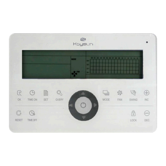
- Page 1 OWNER’S & INSTALLATION MANUAL Centralised Controller KCCT-64 I (B-A) Thank you very much for purchasing our product. Before using your unit, please read this manual carefully and keep it for future reference.
-
Page 2: Table Of Contents
CONTENT 1 Installation part ..................1 1.1 Packing list and installation components ........2 1.2 Installation instructions ..............3 1.3 Installation methods ............... 4 1.4 Safety precautions ................6 1.5 System wiring instruction .............. 7 2 Operation part ..................8 2.1 Function instructions .............. -
Page 3: Installation Part
INSTALLATION PART Installation & Owner‘s Manual... -
Page 4: Packing List And Installation Components
Packing list and installation components 1. Please check the packing list of the centralized controller,whether the components are complete. Name Quantity Remarks Centralized controller Cross-recessed head tapping GB845/ST3.9*25-C-H(S) screws Fastening plastic expansion pipe Φ6*30 Installation & Operation Manual Matching resistance 120 Ω... -
Page 5: Installation Instructions
Installation instructions Installation instructions 1) Connect 220VAC power to the L、N terminals of the centralized controller directly. 2) Do not lay the signal wire and the power wire of the centralized controller in the same power wire pipe, there should be 300~500mm distance between two pipes. 3) The signal wire of centralized controller should not exceed 1200m. -
Page 6: Installation Methods
Installation methods KCCT-64 I (B-A) Fig.1.1 Centralized controller size (unit: mm) Insert the flathead screwdriver into the concave on the upper side of the box, and rotate slightly to open the upper cover (3 places). Fix the screws of the centralized controller (GB845/ST3.9*25) Base Dial code... - Page 7 FORCED ON EMG.STOP L、N terminals Forced on switch (198V~242V)/(50/60Hz) Emergency stop switch Reserved Communication terminal with air conditioner Fig.1.3 Terminal instruction of centralized controller Installation & Owner‘s Manual...
-
Page 8: Safety Precautions
Safety precautions ■ Safety precautions Read the safety precautions carefully before installing the unit. Stated below are important safety issues that must be obeyed. The meanings of all parts are as follows: Warning Means improper handling may lead to personal injury or property loss. Note Means improper handling may lead to personal death or severe injury. -
Page 9: System Wiring Instruction
System wiring instruction. System wiring diagram of centralized controller and indoor unit of air conditioner. Both of the follo wing wiring modes of centralized controller and indoor unit are applicable: (The number of indoor units connected with each centralized controller is not beyond 64) Indoor unit n3 Indoor unit 1 Indoor unit 2... -
Page 10: Operation Part
OPERATION PART Installation & Owner‘s Manual... -
Page 11: Function Instructions
Function instructions 1. For the new series product, we can connect the indoor CCM controller via XYE port of master outdoor unit of every refrigerant system. Notice that in this case, the outdoor unit must be set to automatic serching address mode. And it will be effective after about 6 minutes. 2. -
Page 12: Power On Or Reset
2. Backlight The backlight will be on by pressing any key except“ ”,when the backlight is off. The backlight will be on,when centralized controller is operating, The backlight will be off, if no key is pressed over 30s. 3. Buzzer When the backlight is on and the centralized controller keys are un-lock, any key (except for the ) is pressed ,the centralized controller will carry on relative function, the buzzer will... -
Page 13: Various Locking
2.3.4 Various locking 1. Centralized controller locking The centralized controller locking state will be recorded when powered off. It won’t dismiss when re-power on until receiving the unlocking order. 1) Effect ① When the centralized controller is under locking state, it can not change the air conditioner’s operating state through the centralized controller (such as ON/OFF the unit, setting mode, change the setting temperature, change the fan speed, unlock the exiting locking state etc), but it can do the query operation, until unlocking and then recover to normal. -
Page 14: On And Off
3. Mode locking 1) Effect Under mode locking state, through centralized controller to operate the air conditioner, only can choose the mode which has not conflict with locking mode. 2) Operation Can set the heating mode locking or cooling mode locking. Under mode locking state, if set the new mode locking, it must be unlocking first, then can operate the new mode locking. - Page 15 2. Use “ ” key to ON and OFF the unit Only can operate all the air conditioners in the centralized controller network, not for single air conditioner. “ ” key long press: press this key for over 2 seconds then loose. “...
-
Page 16: Operation Instructions
Instruction of electric control function Keys of centralized controller Installation & Owner‘s Manual... -
Page 17: Keys Instructions
2.4.1 Key operaion instruction 1. Query key “ ” Any time when you press the key, the selected operation mode is to query the operation status of the air conditioner. By default, the first in-service air conditioner will be queried. 2. - Page 18 9. Rightward key “ ” In the query mode, when the key is pressed, the next in-service air conditioner is selected,and its operation status data will be displayed.If it is currently on the last air conditioner, the first one is selected and its data displays, when the key is pressed. If this key is hold down long, the address will increase one by one.
- Page 19 13. Reduce key “ ” 1) Query mode Pr ess this “ ” key, display the data of the previous page. If it is now in the first page, press the key “ ” again and the last page will be displayed.
- Page 20 Installation & Owner‘s Manual...
-
Page 21: Lcd Instructions
2.4.2 LCD instruction 1. General display data 1) General display data is displayed in all display pages. ① The icon displayes in the cycle: (blank) → → (blank),when thecentralized controller communicates with the network interface normally. ② The icon “ ”... - Page 22 a. The array of the liquid crystal display is composed of 4X16 grids, and each grid is composed of two blocks of different sizes (as shown in the above figure). The status indication table is as follows: Status Constantly on Slow blink Fast blink Not bright Object Big black...
- Page 23 2) Description of the query page Fig 2.6 The example diagram of the query page ① The LCD display shows the query page, and the air conditioner with the address of 01 is being queried. ② Mode of the air conditioner with the address 01 is: Cooling, strong air, swing on, indoor temperature 22°C, set temperature 20°C, cooling mode “lock”.
-
Page 24: Other Instructions
Fault page display description Fig 2.8 The example diagram of fault page ① Query the air conditioner with the address of 08 in the query page. ② The air conditioner with the address of 08 is faulty, and fault code is 08. The big black dot below (00+,08) blinks. - Page 25 00 01 02 03 04 05 06 07 08 09 10 11 12 13 a. Function selection b. Parameter selection c. Reminding d. “Set successfully” reminding Fig 2.9 Filter net in addition to the dust function involves of show a contents 2) Function setting ①...
-
Page 26: Error Code Table
2.4.4 Fault and protection code table Fault code Fault content Description Other faults Water level detection faults Reserved Cleaning fault Inverter module protection Over-current of compressor(4 times) Fault of communication between main board and display board Air speed detection out of control EEPROM error Zero crossing detection error Outdoor unit fault protection... -
Page 27: Technical Index And Requirements
Technical indices and requirements 1. EMC, EMI comply with the CE certification requirements. 2. Electrical safety comply with GB4706.32-2004, GB/T7725-2004. 16111500000910 V.E Installation & Owner‘s Manual...
Need help?
Do you have a question about the KCCT-64 I B and is the answer not in the manual?
Questions and answers