
Related Manuals for Kaysun KCTAQ-01


Summary of Contents for Kaysun KCTAQ-01
- Page 1 OWNER'S MANUAL Central Heat Pump Heater Wire Controller KCTAQ-01 Thank you very much for purchasing our product. Before using the unit, please read this manual carefully and keep it for future reference.
- Page 2 ● This manual gives detailes description of the precautions that should be brought to your attention during operation ● To ensure correct service of the wiring controller please read this manual carefully before using the unit ● For convenience of future reference, keep this manual after reading it...
-
Page 3: Table Of Contents
CONTENTS PAGE 1 GENERAL SAFETY PRECAUTIONS .......... 1 2 A GLANCE OF THE USER INTERFACE ........3 3 USING HOME PAGES ..............5 4 MENU ................... 9 5 BASIC USAGE ................10 6 MENU ..................20 7 INSTALLATION MANUAL ............58 8 MENU STRUCTURE: Overview .......... -
Page 4: General Safety Precautions
1 GENERAL SAFETY PRECAUTIONS 1.1 About the documentation The precautions described in this document cover very important topics, follow them carefully. 1.1.1 Meaning of warnings and symbols DANGER Indicates a situation that results in serious injury. DANGER: RISK OF ELECTROCUTION Indicates a situation that could result in an electric shock. DANGER: RISK OF BURNING Indicates a situation that could result in burning because of extreme hot or cold temperatures. - Page 5 1.2 For the user If you are not sure how to operate the unit, contact your installer. The appliance is not intended for use by persons, including children, with reduced physical, sensory or mental capabilities, or lack of experience and knowledge, unless they have been given supervision or instruction concerning use of the appliance by a person responsible for their safety. Children must be supervised to ensure that they do not play with the product. CAUTION Do NOT apply water to the unit. This may cause electric shocks or fire. Units are marked with the following symbol: This means that electrical and electronic products may not be mixed with unsorted household waste. Do NOT try to dismantle the system yourself: the dismantling of the system, treatment of the refrigerant, of oil and of other parts must be done by an authorized installer and must comply with applicable legislation. Units must...
-
Page 6: Glance Of The User Interface
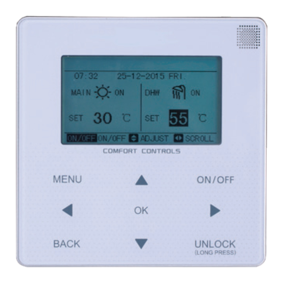
2 A GLANCE OF THE USER INTERFACE 2.1 The appearance of the wire control device Enter the menu Turn the space structure from operation mode the home or DHW mode on page or off in the menu Navigate the cursor on the display/navigate in the menu structure/ adjust... - Page 7 2.2 Status icons The disinfect function is activated Prevent freezing icon An AHS Holiday away/home is activated (additional heating source such as a gas boiler) is activated Silent mode is activated Timer icon Backup heater is activated A malfunction has occurred The compressor is activated Lock icon Shutoff...
-
Page 8: Using Home
3 USING HOME PAGES 3.1 About home pages You can use the home pages to read out and change settings that are meant for daily usage. What you can see and do on the home pages is described where applicable. Depending on the system layout, the following home pages may be possible: ■ Room temperature (ROOM) ■ Outlet water temperature (MAIN) ■ D HW tank temperature (TANK) DHW=domestic hot water home page1: If the WATER FLOW TEMP. is set YES and ROOM TEMP. is set NON. (See FOR SERVICEMAN TEMPERATURE TYPE SETTING on installation & owner's manual). There will be only main page. The system has the function including floor heating and domestic water. - Page 9 home page2: If you have set the WATER FLOW TEMP. is set NON and ROOM TEMP. is set YES (See FOR SERVICE TEMPERATURE TYPE SETTING on installation & owner's maunal). There will be only main page. The system has the function including floor heating and domestic hot water. The page will appear: NOTE: The interface should be installed in the floor heating room to check the room temperature. the system layout 2 21: 55 08 - 08 - 2015 SAT. ROOM TANK home page3: If the WATER FLOW TEMP. is set YES and ROOM TEMP. is set YES (See FOR SERVICEMAN TEMPERATURE TYPE SETTING on installation & owner's manual). There will be main page and additional page. The system has the function including floor heating and space cooling for fan coil. The page will appear:...
- Page 10 the system layout 3 MAIN 21: 55 08 - 08 - 2015 SAT. PAGE MAIN 21: 55 08 - 08 - 2015 SAT. ROOM ADDITIONAL PAGE home page4: If you have set the WATER FLOW TEMP to YES and ROOM TEMP to YES There will be a main page and an added page. The system has the functions of floor heating, air conditioning, and water heating. This page will appear: the system layout 4 MAIN PAGE 21: 55 08 - 08 - 2015 SAT. MAIN TANK 21: 55 08 - 08 - 2015 SAT.
- Page 11 home page5: If you have set the WATER FLOW TEMP to YES and ROOM TEMP to YES There will be a main page and an added page. The system has the function of air conditioning. This page will appear: MAIN 21: 55 08 - 08 - 2015 SAT. PAGE MAIN 21: 55 08 - 08 - 2015 SAT. ADDITIONAL ROOM PAGE...
-
Page 12: Menu
4 MENU 4.1 About the menu structure You can use the menu structure to read out and configure settings that are NOT meant for daily usage. What you can see and do in the menu structure is described where applicable. For an overview of the menu structure, see "7 MENU STRUCTURE: Overview". 4.2 To go to the menu From a home page, press ''MENU''. Result: The menu will appear: MENU MEMU OPERATE MODE SERVICE INFORMATION PRESET TEMPERATURE OPERATION PARAMETER DOMESTIC HOT WATER(DHW) FOR SERVICEMAN... -
Page 13: Basic Usage
5 BASIC USAGE 5.1 Screen Unlock If the icon is on the screen, the controller is locked. This page is displayed: 21: 55 08 - 08 - 2015 SAT. MAIN TANK Press any key and the icon will flash. Long press ''UNLOCK'' key, the icon will disappear, and the interface can be controlled. 21: 55 08 - 08 - 2015 SAT. MAIN TANK The interface will be locked if there is no handing for a long time (about 60 seconds: it can be set... - Page 14 21: 55 08 - 08 - 2015 SAT. MAIN TANK long press long press UNLOCK UNLOCK UNLOCK UNLOCK 21: 55 08 - 08 - 2015 SAT. MAIN 55 C TANK 5.2 Turning ON/OFF controls Use the interface to turn the unit on and off the unit for space heating or cooling. ■ The ON/OFF of the unit can be controlled by the interface if the ROOM THERMOSTAT is NON.
- Page 15 21: 55 08 - 08 - 2015 SAT. MAIN TANK 1) When the cursor is ON space operation mode (Including heat mode , cool mode and auto mode ) , press the ''ON/OFF'' key to turn on/off the operation mode. 21: 55 08 - 08 - 2015 SAT. 21: 55 08 - 08 - 2015 SAT.
- Page 16 21: 55 08 - 08 - 2015 SAT. 21: 55 08 - 08 - 2015 SAT. MAIN MAIN ON/OFF 21: 55 08 - 08 - 2015 SAT. 21: 55 08 - 08 - 2015 SAT. ROOM ROOM ON/OFF...
- Page 17 Use the room thermostat to turn the unit on and off for space heating or cooling. The room thermostat is SET YES (see ROOM THERMOSAT in the Installation & Owner’s manual). The unit is turned on or off using the room thermostat. Press on/off on the interface and the page will display: 22:20 22-08-2018 SAT Cool/heat mode is controlled by the room thermostat. The cool or heat mode is closed.
- Page 18 Use the interface to turn the unit on or off for DHW. Press ''►'', ''▼''on home page and the black cursor will appear: 21: 55 08 - 08 - 2015 SAT. MAIN TANK 2) When the cursor is in DHW mode. Press the ''ON/OFF'' key to turn DHW mode on/off. 21: 55 08 - 08 - 2015 SAT. 21: 55 08 - 08 - 2015 SAT. MAIN MAIN TANK...
- Page 19 5.3 Adjusting the temperature Press ''◄'', ''▲'' on the home page and the black cursor will appear: 21: 55 08 - 08 - 2015 SAT. MAIN 55 C TANK ON/OFF ADJUST SCROLL ON/OFF ■ I f the cursor is on temperature, use the ''◄'', ''►" to select and use "▼'', ''▲'' to adjust the temperature.
- Page 20 21: 55 08 - 08 - 2015 SAT. 21: 55 08 - 08 - 2015 SAT. MAIN MAIN TANK TANK ON/OFF ADJUST SCROLL ON/OFF ADJUST SCROLL ON/OFF ON/OFF 21: 55 08 - 08 - 2015 SAT. MAIN 21: 55 08 - 08 - 2015 SAT. ROOM TANK ON/OFF...
- Page 21 5.4 Adjusting the space operation mode ■ A djusting space operation mode on the interface. Go to ''MENU'' > ''SPACE OPERATION MODE''. Press "OK" and this page will appear: OPERATION MODE Operation mode setting: HEAT AUTO COOL CONFIRM SCROLL ■ T here are three modes to be selected including heat, cool, and auto mode. Use the ''◄'', ''►'' to scroll and press "OK” to select. Even you don’t press OK button and exit the page by pressing BACK button. The mode is also effective if the cursor must be moved to the operation mode. If there is only heat(cool) mode, this page will appear: OPERATION MODE Operation mode setting: HEAT CONFIRM SCROLL...
- Page 22 If you Then the space operation mode is… select… Always heat mode heat Always cool mode cool Automatically changed by the software based on the outdoor temperature (and depending on installer settings also the indoor temperature). It takes monthly restrictions into account. auto Note: Automatic changeover is only possible under certain conditions. See the FOR SERVICEMAN > AUTO MODE SETTING on installation & owner's manual. ■ A djust the space mode on the room thermostat to see room thermostat in the installation &...
-
Page 23: Menu
6 MENU 6.1 Operation Mode See "5.4 OPERATION MODE" 6.2 Preset Temperature PRESET TEMPERATURE has PRESET TEMP\WEATHER TEMP.\ECO MODE 3 items. 6.2.1 PRESET TEMP. PRESET TEMP. function is used to set different temperature on different time when the heat mode or cool mode is on. ■ P RESET TEMP. = PRESET TEMPERATURE ■ T he PRESET TEMP. function will be off in these conditions 1) AUTO mode is running. 2) TIMER or WEEKLY SCHEDULE is running. ■ G o to "MENU" > "PRESET TEMPERATURE" > "PRESET TEMP". press "OK". The following page will appear: Use ''◄'', ''►", "▼'', ''▲'' to scroll and use "▼'', ''▲'' to adjust the time and the temperature. When the cursor is on " ", as the following page:... - Page 24 Press "OK", ant the " " becomes " ". The timer 1 is selected. Press "OK" again, the " " becomes " ". The timer 1 is unselected. Use ''◄'', ''►", "▼'', ''▲'' to scroll and use "▼'', ''▲'' to adjust the time and the temperature. Set six periods and six temperatures can be set. For example: Now time is 8:00 and temperature is 30ºC. We set the PRESET TEMP as follows table. The following page will appear:...
- Page 25 TIME TEMPER 8:30 35ºC 9:00 25ºC 10:00 35ºC 11:00 25ºC 12:00 35ºC 13:00 25ºC INFORMATION ■ W hen the space operation mode is changed the PRESET TEMP. is off automatically. ■ T he PRESET TEMP. function can be used in the heat mode or cool mode. But if the operation mode is changed, the PRESET TEMP. function need reset again. ■ T he running preset temperature is invalis when the unit is OFF. It will run according to the next preset temperature when the unit turn on again.
- Page 26 6.2.2 WEATHER TEMP. SET ■ W EATHER TEMP. SET = WEATHER TEMPERATURE SET ■ W eather temp. set function is used to preset the desired the water flow temperature automatically depending on the outside air temperature. During the warmer weather the demand for space heating is reduced. To prevent the heat pump from producing excessing water flow temperature for the primary circuit. the weather temp. set can be used to maximize efficiency and reduce running costs. Go to "MENU" > "PRESET TEMPERATURE" > "WEATHER TEMP. SET". Press "OK".
- Page 27 INFORMATION ■ W EATHER TEMP. SET have four kinds of curves: 1.the curve of the high temperature setting for heating, 2.the curve of the low temperature setting for heating, 3.the curve of the high temperature setting for cooling, 4.the curve of the low temperature setting for cooling. It only has the curve of the high temperature setting for heating. if the high temperature is set for heating.
- Page 28 Use ''◄'', ''►" to scroll. Press "OK" to select ■ I f the weather TEMP. SET is activated, desired temperature can not be adjusted on the interface. Press the "▼'', ''▲'' to adjusr the temperature on home page. The following page will appear: Move to "NO", press "OK" to come back to home page, move to "YES", press "OK" to reset the WEATHER TEMP. SET.
- Page 29 6.2.3 ECO MODE Use ECO MODE is used to save energy. If ECO mode is activated, is displayed on the home page. Go to "MENU" > "PRESET TEMPERATURE" > "ECO MODE". Press "OK". The following page will appear: Press "ON/OFF". The following page will appear: Use ''◄'', ''►" to scroll. Press "OK" to select...
- Page 30 INFORMATION ■ E CO MODE SET have two kinds of curves: 1.the curve of the high temperature setting for heating, 2.the curve of the low temperature setting for heating. It only have the curve of the high temperature setting for heating, if the high temperature is set for heating. It only have the curve of the low temperature setting for heating, if the low temperature is set for heating.
- Page 31 Use ''◄'', ''►", "▼'', ''▲'' to scroll and use "▼'', ''▲'' to adjust the parameters when setting "OPERATE DAY" and "START". If the OPERATE DAY is set FRIDAY and the START is set 23:00, the disinfect function will active on 23:00 Friday.
- Page 32 If CURRENT STATE is OFF, DISINFECT is invalid. If the disinfect function is running, the following page will appear: 6.3.2 Fast DHW The FAST DHW function is used forced the system to operation in DHW mode. The heat pump and the booster heater or backup heater will operate for DHW mode together. Go to MENU > DOMESTIC HOT WATER > FAST DHW. Press "OK":...
- Page 33 Use "ON/OFF key to select ON or OFF. INFORMATION If CURRENT STATE is OFF, the FAST DHW is invalid, and if CURRENT STATE is ON, the FAST DHW function is effective. The FAST DHW function is once effective.
- Page 34 6.3.3 HEATER TANK The tank heater is used to force the tank heater to heat the water in tank. In the same situation, the cooling or heating is required and the heat pump system is operating for cooling or heating, however there still is a demand from the hot water. TANK HEATER function can be used to heat the water in tank. Also, even if the heat pump system fails, TANK HEATER can be used to heat water in tank. Go to "MENU" > "DOMESTIC HOT WATER" > "TANK HEATER". Press "OK".
- Page 35 Use "ON/OFF" to select ON or OFF. Use "BACK" to exit. If TANK HEATER is effect, the following page will appear: INFORMATION If CURRENT STATE is OFF, TANK HEATER is invalid. If the T5 (sensor of tank) is fault, tank heater can't work. 6.3.4 DHW Pump The DHW PUMP function is used to return water of the water net. Go to "MENU" > "DOMESTIC HOT WATER" > "DHW PUMP". Press "OK". The following page will appear:...
- Page 36 Move to " ", press "OK" to select or unselect. (" " the timer is selected. " " the timer is unselected). Use ''◄'', ''►", "▼'', ''▲'' to scroll and use "▼'', ''▲'' to adjust the parameters. For example: you have set the parameter about the DHW PUMP (See FOR SERVICEMAN TEMPERATURE TYPE SETTING on installation& owner's manual). PUMP RUNNING TIME is 30 minutes. Set as follows: START...
- Page 37 The PUMP will run as follows: 6.4 Schedule SCHEDULE menu contents as following: 1) TIMER to set the day schedule 2) WEEKLY SCHEDULE to set the weekly schedule 3) TIME to set the current time and date 6.4.1 Disinfect If the weekly schedule function is on, the timer is off, the later setting is effective. If the Timer is activated, is displayed on home page...
- Page 38 Use ''◄'', ''►", "▼'', ''▲'' to scroll and use "▼'', ''▲'' to adjust the time, the mode and the temperature. Move to " ", press "OK" to select or unselect. (" " the timer is selected. " " the timer is unselected) six timers can be set. If you want to cancel the TIMER, you move the cursor to " ", press "OK", the become , the timer is invalid.
- Page 39 Example: Six timer is set as following: START MODE TEMP 1:00 3:00 50ºC 7:00 9:00 HEAT 28ºC 11:30 13:00 COOL 20ºC 14:00 16:00 HEAT 28ºC 15:00 19:00 COOL 20ºC 18:00 23:00 50ºC The unit will run as following: The operation of the controller at the following time: Time The operation of the controller 1:00 DHW mode is turned ON 3:00 DHW mode is turned OFF 7:00 HEAT MODE is turned ON 9:00 HEAT MODE is turned OFF...
- Page 40 INFORMATION If the start time is same to the end time in one timer, the timer is invalid. 6.4.2 Weekly schedule If the timer function is on the weekly schedule is off, the later setting is effective. If WEEKLY SCHEDULE is activated, is displayed on the home page. Go to "MENU" > "SCHEDULE" > "WEEKLY SCHEDULE". Press "OK". The following page will appear: First select the days of the week, you wish to schedule.
- Page 41 Use ''◄'', ''►" move to SET, press "OK". The Monday to Friday are selected to be scheduled and they have the same schedule. The following pages will appear:...
- Page 42 Use ''◄'', ''►", "▼'', ''▲'' to scroll and adjust the time, the mode and the temperature. Timers can be set, including start time and end time, mode and temperature. The mode includs heat mode, cool mode and DHW mode. The setting method reffer to timer setting. The end time must be later than the start time. Otherwise this will show that Timer is of no effect. How to cancel the WEEKLY SCHEDULE Cancel the schedule: First select the days of the week. Use ''◄'', ''►" to scroll.
- Page 43 INFORMATION You have to reset TIMER/WEEKLY SCHEDULE, if you change the MAIN page to the ROOM page or you change the ROOM page to the MAIN page. The TIMER or WEEKLY SCHEDULE is invalid, if ROOM THERMOSTAT is effect. 6.4.3 Time The TIME function is used to set the local actual time and date. Go to "MENU" > "SCHEDULE" > "TIME". Press "OK". The following page appear: Use ''◄'', ''►", "▼'', ''▲'' to scroll and use "▼'', ''▲'' adjust the time and date.
- Page 44 INFORMATION ■ T he ECO or COMFORT MODE has the highest priority, the TIMER or WEEKLY SCHEDULE has the second priority and the PRESET TEMP. or WEATHER TEMP. SET has the lowest priority. ■ T he PRESET TEMP. or WEATHER TEMP. SET becomes invalid, when we set the ECO or COMFORT valid. We must reset the PRESET TEMP. or WEATHER TEMP. SET when we set the ECO or COMFORT valid. ■ T IMER or WEEKLY SCHEDULE is not affected when ECO or COMFORT is valid. TIMER or WEEKLY SCHEDULE is activated when the ECO or COMFORT is not running. ■ T IMER and WEEKLY SCHEDULE are the same priority. The after setting function is valid. The PRESET TEMP. becomes invalid when TIMER or WEEKLY SCHEDULE is valid. The WEATHER TEMP. SET is not affected by the setting of TIMER or WEEKLY SCHEDULE.
- Page 45 6.5.1 Silent Mode The SILENT MODE is used to decrease the sound of the unit. However, it also decreases the heating/cooling capacity of the system. Thwew are two silent mode levels. level2 is more silent than level1, and the heating or cooling capacity is also more decreasing. There are two method to use the silent mode: 1) silent mode in all time; 2) silent mode in timer. ■ G o to the home page to check if silent mode is activated. If is displayed, if the silent mode is will display on the home page.
- Page 46 You can use "▼'', ''▲'' to select level 1 or level 2. Press "OK". If the silent TIMER is selected. Press "OK" to enter, the following page will appear.
- Page 47 There are two timers for setting. Move to " ", press "OK" to select or unselect. If the two time are both unselected, the silent mode will operate in all time. Otherwise, it will operate according as the time. 6.5.2 Holiday Away ■ I f the holiday away mode is activated, will display on the home page. The holiday away function is used to prevent frozen in the winter during the outside holiday, and return the unit before the end of the holiday. Go to "MENU" > "OPTIONS" > "HOLIDAY AWAY". Press "OK". The follwing page will appear.
- Page 48 Usage example: You go away during the winter. The current date is 2016-01-31, two days later is 2016-02-02, it is the beginning date of the holiday. If you are in the following situation: ■ I n 2 days, you go away for 2 weeks during the winter. ■ Y ou want to save energy, but prevent your house from freezing. Then you can do the following: 1) Configure the holiday. Configure the following settings: SETTING VALUE Holiday away From 2 February 2016 Until 16 February 2016 Operation mode Heating Disinfect 2) Activate the holiday mode. G o to "MENU" > "OPTIONS" > "HOLIDAY AWAY". Press "OK". Use "ON/OFF" to select "OFF" or "ON" and use ''◄'', ''►", "▼'', ''▲'' to scroll and adjust.
- Page 49 INFORMATION ■ I f DHW mode in holiday away mode is ON, the disinfect set by user is invalid. ■ I f holiday away mode is ON, the timet and weekly schedule are invalid except exit. ■ I f the CURRENT STATE is OFF, the HOLIDAY AWAY is OFF. ■ I f the CURRENT STATE is ON, the HOLIDAY AWAY is ON. ■ T he remote control doesn't accept any orders when holiday away mode is ON. ■ D isinfecting the unit on 23:00 of the last day if disinfect is ON. ■ W hen in holiday away mode, the climate related curves previously set is invalid, and the curves will automatically take effect after the holiday away mode is end. ■ T he preset temperature is invalid when in holiday away mode, but the preset value still display on the main page. 6.5.3 Holiday Home The holiday home function is used to deviate from the normal schedules without having to change them during the holiday at home. ■ D uring your holiday, you can use the holiday mode to deviate from your normal schedules without having to change them PERIOD...
- Page 50 Use "ON/OFF" to select "OFF" or "ON" and use ''◄'', ''►", "▼'', ''▲'' to scroll and adjust. If the CURRENT STATE is OFF, the HOLIDAY HOME is OFF. If the CURRENT STATE is ON, the HOLIDAY HOME is ON. Use "▼'', ''▲'' to adjust the date. ■ B efore and after your holiday, your normal schedule will be used. ■ D uring your holiday, you save energy and prevent your house from freezing. INFORMATION You have to reset Holiday away or Holiday home, if you change the unit whether or not have the function of DHW or HEAT. 6.5.4 Backup Heater ■ T he BACKUP HEATER function is used to force the backup heater. Go to "MENU" > "OPTIONS" > "BACKUP HEATER". Press "OK". If the HEATER is set NON in "OTHER HEATING SOURCE". The following page will appear:...
- Page 51 ■ I f the HEATER is set YES in "OTHER HEATING SOURCE", the following page will appear: Use "ON/OFF" to select "OFF" or "ON" and use "▼'', ''▲'' to scroll.
- Page 52 INFORMATION ■ I f the operation mode is auto mode in space heating or cooling side, the backup heater function can not be selected. ■ T he BACKUP HEATER function is in invalid when only ROOM heat mode enabled. 6.6 CHILD LOCK The CHILD LOCK function is used to prevent children error operation. The mode setting and temperature adjusting can be locked or unlocked by use CHILD LOCK function. Go to "MENU" > "CHILD LOCK". The page is displayed: Input the current password, the following page will appear:...
- Page 53 Use "▼'', ''▲'' to scroll and "UNLOCK" to select LOCK or UNLOCK. The temperature can't be adjusted when the temperature is locked. The mode can't be changed when the mode is locked. If you want to change them, you must unlock them use the CHILD LOCK function. 6.7 Service information 6.7.1 About service information Service information menu contents as following: 1) service call: to check service call for contacting; 2) error code: to check the error code mean; 3) parameter: to review the operation parameters; 4) display: to set the display. 6.7.2 How to go to service information menu ■ G o to "MENU" > "SERVICE INFORMATION". Press "OK". The following page will appear: ■ T he service call can show the service phone or mobile number. The installer can input the phone number. See FOR SERVICEMAN.
- Page 54 Error code is used to show when the fault or portion happen and show the mean of the error code. Press OK the page will appear: INFORMATION ■ A total of eight fault codes can be recorded.
- Page 55 Press OK to show the mean of the error code: The parameter function is used to display the main parameter, there are two pages to show the parameter:...
- Page 56 The display function is used to set the interface, the main items is language, backlight, buzzer and screen lock time: Use "OK" to enter and use ''◄'', ''►", "▼'', ''▲'' to scroll. Information: Now there is only one language English in the interface.
- Page 57 6.8 Operation Parameter This menu is for installer or service engineer reviewing the operaiton parameter. ■ A t home page, go to "MENU" > "OPERATION PARAMETER". ■ P ress "OK". There are five pagews for the operating paramter as following. Use "▼'', ''▲'' to scroll.
- Page 59 INFORMATION The power consumption parameter is preparatory. If some parameter is not activated in the system, the parameter will show "--". 6.9 For Serviceman 6.9.1 About For Serviceman FOR SERVICEMAN is used for installer and service engineer. ■ S etting the composition of equipment. ■ S etting the parameters. 6.9.2 How to go to For Serviceman Go to "MENU" > "FOR SERVICEMAN". Press "OK" ■ T he FOR SERVICEMAN is used for installer or service engineer. It is NOT intended the home owner alters setting with this menu. ■ I t is for this reason password protection is required to prevent unauthorized access to the service settings.
- Page 60 6.9.3 How to exit For Serviceman If you have set all the parameter. Press "BACK", the following page will be appear: Select "YES" and press "OK" to exit the FOR SERVICEMAN. After exiting the FOR SERVICEMAN, the unit will be turned off.
-
Page 61: Installation Manual
7 INSTALLATION MANUAL 7.1 Safety Precautions ■ R ead the safety precautions carefully before installing the unit. ■ I mportant safety issues are as follows ■ C onfirm everything is normal during testing, then hand the manual to the user ■ M eaning of marks: WARNING Means improper handling may lead to severe injury. CAUTION Means improper handling may lead to injury or property loss. WARNING Entrust the distributor or a technician to install the unit. Installation by anyone else may lead to faulty installation, electric shocks or fires. - Page 62 CAUTION Do not install the unit in a place that is vulnerable to flammable gas. If flammable gases leak around the wired controller, a fire may occur. The wiring should adapt to the wired controller's current. Otherwise, electric leaks or heating may occur and result in a fire. The specified cables must be used for wiring. Do not apply any external force may on the terminal.
- Page 63 7.2.3 Note for installing the wired controller: 1) T his installation manual contains information about the procedure for installing the Wired Controller. Refer to the Indoor Unit Installation Manual for connecting the Wired Controller and the Indoor Unit. 2) T he circuit of the Wired Controller is low voltage. Never connect it to a standard 220V/380V circuit or place it into a same Wiring Tube as the circuit.
- Page 64 7.3.2 Wiring Main Unit control box wired controller Input Voltage(A/B) 13.5VAC Wiring size 0.75mm...
- Page 65 7.3.3 Back cover installation Buckling position Back cover Front cover Straight head screwdriver For the screw holes in the wall, use three GB950-86 M4X20 screws...
- Page 66 For the screw holes in the wall, use one GB950-86 M4X20 screw For the screw holes on the 86 Electrician box, use two M4X25 GB823-88 screws Back cover Signal switching wires...
- Page 67 1) U se a straight head screwdriver to insert the 7.3.4 Wire outlet buckling position in the bottom of the wired controller, and unscrew the screws to remove the back cover. (Pay attention to the rotation direction, or you will damage the back cover). 2) U se three GB950-86 M4X20 screws to fix the back cover to the wall. 3) U se two M4X25 GB823-88 screws to install the back cover on the 86 electrician box. Use one GB950-86 M4X20 screw to screw it on the wall.
- Page 68 Wall hole and wiring hole 60 mm Wiring Diameter:Φ8--Φ10 hole Putty Trap Putty Putty Do not let water enter the wired controller. Use trap and putty to seal the connectors of wires Trap during wiring installation. Trap...
- Page 69 7.4 Front cover installation After adjusting the front cover and the buckling the front cover, avoid clamping the communication switching wire during installation. Sensors must avoid moisture.
- Page 70 Correctly install the back cover and firmly buckle the front cover and back cover, otherwise the front cover will fall off.
-
Page 71: Menu Structure: Overview
8 MENU STRUCTURE: Overview MENU SPACE OPERATION MODE SPACE OPERATION MODE HEAT PRESET TEMPERATURE COOL DOMESTIC HOT WATER (DHW) AUTO SCHEDULE OPTIONS PRESET TEMPERATURE CHILD LOCK PRESET TEMP. SERVICE INFORMATION WEATHER TEMP. SET OPERATION PARAMETER ECO MODE FOR SERVICEMAN DOMESTIC HOT WATER (DHW) DISINFECT DISINFECT FAST DHW... - Page 72 1.1 DHW MODE 1 DHW MODE SETTING dT5 on 1.1 DHW MODE INSTALLATION MENU dT1S5 1.2 TANK HEATER 1 DHW MODE SETTING T4DHWMAX 1.3 DISINFECT 2 COOL MODE SETTING T4DHWMIN 1.4 DHW PRIORITY 3 HEAT MODE SETTING t_INTERVAL_DHW 1.5 DHW PUMP 4 AUTO MODE SETTING 5 TEMP.
- Page 73 Table1 The environment temperature curve of the low temperature setting for heating ≤-20 1-T1S 2-T1S 3-T1S 4-T1S 5-T1S 6-T1S 7-T1S 8-T1S ≥20 1-T1S 2-T1S 3-T1S 4-T1S 5-T1S 6-T1S 7-T1S 8-T1S Table2 The environment temperature curve of the high temperature setting for heating ≤-20 1-T1S 2-T1S...
- Page 74 Table3 The environment temperature curve of the low temperature setting for cooling -10≤T4<15 15≤T4<22 22≤T4<30 30≤T4<46 1-T1S -10≤T4<15 15≤T4<22 22≤T4<30 30≤T4<46 2-T1S -10≤T4<15 15≤T4<22 22≤T4<30 30≤T4<46 3-T1S -10≤T4<15 15≤T4<22 22≤T4<30 30≤T4<46 4-T1S -10≤T4<15 15≤T4<22 22≤T4<30 30≤T4<46 5-T1S -10≤T4<15 15≤T4<22 22≤T4<30 30≤T4<46 6-T1S -10≤T4<1524...
- Page 75 Table 5 The environment temperature curve of the low temperature setting for ECO mode ≤-20 ≥20 Table6 The environment temperature curve of the high temperature setting for ECO mode ≤-20 ≥20...
-
Page 76: Appendix
9 Appendix Modbus Mapping Table... - Page 77 6-3 Modbus Port Communication Specifications: Port: RS-485; the wired controller XYE is the communication port for connecting with the hydraulic module. H1 and H2 are the Modbus communication ports. Communication address: It is consistent with the DIP switch address of the hydraulic module. Baud rate: 4800, 9600, 19200, 38400. The default setting is 9600. Number of digits: Eight Verification: Odd, even, none Stop Bit: 1 bit, 2 bits Communication protocol: Modbus RTU (Modbus ASCII is not supported) Default configuration: 9600, N, 8, 1 (i.e. the baud rate is 9600, no verification, eight bits, one stop bit)
- Page 78 1 Mapping of registers in the wired controller The following addresses can use 03H, 06H (write single register), 10H (write multiple register) Register Description Remarks address Power on or off. BIT15 Reserved BIT14 Reserved BIT13 Reserved (PLC:40001) BIT12 Reserved BIT11 Reserved BIT10 Reserved BIT9 Reserved BIT8 Reserved BIT7 Reserved BIT6 Reserved BIT5 Reserved BIT4 Reserved BIT3 Reserved BIT2 0: DHW(T5S) power off; 1: DHW(T5S) power on...
- Page 79 1 (PLC:40002) Setting the mode 1: Auto; 2: Cool; 3: Heat; Others: Invalid Setting water temperature Water temperature T1s is corresponding to the floor heating. (PLC:40003) Setting air temperature Ts The room temperature ranges between 17°C and 30°C, and is valid when (PLC:40004) there is Ta. 4 (PLC:40005) The water tank temperature range is between 40°C and 60°C. (PLC:40006) BIT15 Function setting Reserved BIT14 Reserved BIT13 Reserved BIT12 1: curve setting is enabled; 0: curve setting is disabled. BIT11 DHW pump's running constant-temperature water recycling BIT10 ECO mode BIT9 Reserved BIT8 Holiday home (the status can only be read, not changed) BIT7 0: Silent mode level1; 1: Silent mode level2 BIT6: Silent mode...
- Page 80 2. W hen the wired controller is connected to the hydraulic module, the parameters of the whole unit can be checked: Whole unit parameter mapping address table 2.1. Running parameters Register address Description Remarks 100 (PLC:40101) Operating frequency Compressor operating frequency in Hz 101 (PLC:40102) Operating Mode Whole unit's actual operating mode, 2: cooling, 3: heating, 0: off 102 (PLC:40103) Fan Speed Fan speed, in r/min PMV openness...
- Page 81 Status bit 1 BIT15 Reserved (PLC:40129) BIT14 Reserved BIT13 Reserved BIT12 Reserved BIT11 Reserved BIT10 Reserved BIT9 Reserved BIT8 Solar energy signal input BIT7 Room temperature controller cooling BIT6: Room temperature controller heating BIT5: Outdoor unit test mode mark BIT4: Remote On/Off (1: d8) BIT3: Oil return...
- Page 82 2.2 Parameter setting Register Remarks Description address 200 (PLC:40201) RemarksThe upper 8 bit is the home appliance type: Home appliance type Central heating: 0x07 201 (PLC: 40202) Temperature upper limit of T1S cooling 202 (PLC: 40203) Temperature lower limit of T1S cooling 203 (PLC: 40204) Temperature upper limit of T1S heating 204 (PLC: 40205) Temperature lower limit of T1S heating 205 (PLC: 40206) Temperature upper limit of TS setting 206 (PLC: 40207) Temperature lower limit of TS setting 207 (PLC: 40208) Temperature upper limit of water heating 208 (PLC: 40209)
- Page 83 BIT15 Supports backup heater (IBH) 211 (PLC:40212) Parameter setting 2 BIT14 IBH supports heating BIT13 IBH supports water heating BIT12 Supports AHS BIT11 AHS supports heating BIT10 AHS supports water heating BIT9 Supports solar energy module BIT8 Reserved BIT7 Reserved BIT6: Reserved BIT5: Reserved BIT4: Reserved BIT3: Reserved BIT2: Reserved BIT1: Reserved BIT0:...
- Page 84 t_DI_max Maximum disinfection duration, range: 90~300 min, default setting: 210 min 221 (PLC: 40222) t_DI_hightemp 222 (PLC: 40223) Disinfection high temperature duration, range: 5~60 min, default setting: 15 min t_interval_C Time interval of compressor start-up in cooling mode; range: 5~30 min, 223 (PLC: 40224) default setting: 5 min dT1SC 224 (PLC: 40225) Default setting: 5°C, range: 2~10°C, setting interval: 1°C dTSC 225 (PLC: 40226) Default setting: 2°C, range: 1~10°C, setting interval: 1°C T4cmax 226 (PLC: 40227) Default setting: 43°C, range: 35~46°C, setting interval: 1°C T4cmin 227 (PLC: 40228) Default setting: 10°C, range: -5~25°C, setting interval: 1°C t_interval_H 228 (PLC: 40229) Time interval of compressor start-up in the heating mode; range: 5~60 min, default setting: 5 min dT1SH Default setting: 5°C, range: 2~10°C, setting interval: 1°C 229 (PLC: 40230) dTSH Default setting: 2°C, range: 1~10°C, setting interval: 1°C 230 (PLC: 40231) T4hmax...
- Page 85 241 (PLC: 40242) t_DHWHP_max Longest duration of water heating by the heat pump, range: 60~600 min, default setting: 180 min; t_DHWHP_restrict 242 (PLC: 40243) Duration of limited water heating by the heat pump, range: 60~600 min, default setting: 180 min; T4autocmin 243 (PLC: 40244) Default setting: 25°C, range: 20~29°C, setting interval: 1°C T4autohmax Default setting: 17°C, range: 10~17°C, setting interval: 1°C 244 (PLC: 40245) T1S_H.A_H In the holiday mode, setting of T1 in the heating mode, range: 245 (PLC: 40246) 20~25°C, default setting: 25°C 246 (PLC: 40247) T5S_H.A_DHW In the holiday mode, setting of T1 in the water heating mode, range: 20~25°C, default setting: 25°C ECO parameter 247 (PLC: 40248) Reserved, wrong address is reported when this register is queried ECO parameter 248 (PLC: 40249) Reserved, wrong address is reported when this register is queried ECO parameter Reserved, wrong address is reported when this register is queried 249 (PLC: 40250)
- Page 86 MD16IU-013AW(Spanish) 16117100A11262...
Need help?
Do you have a question about the KCTAQ-01 and is the answer not in the manual?
Questions and answers