
Related Manuals for Kaysun KC-03.1 SPS


Summary of Contents for Kaysun KC-03.1 SPS
- Page 1 USER AND INSTALLATION MANUAL KC-03.1 SPS Thank you very much for purchasing our product. Before using your unit, please read this manual carefully and keep it for future reference.
- Page 2 ● This manual gives detailed description of the precautions that should be brought to your attention during operation. ● In order to ensure correct service of the wired controller please read this manual carefully before using the unit. ● For convenience of future reference, keep this manual after reading it.
-
Page 3: Table Of Contents
CONTENTS 1. SAFETY PRECAUTION................4 2. INSTALLATION ACCESSORY..............5 3. INSTALLATION METHOD................. 6 4. SPECIFICATION ..................9 5. FEATURE AND FUNCTION OF THE WIRED CONTROLLER… ..10 6. NAME ON THE LCD OF THE WIRE CONTROLLER......11 7. NAME OF BUTTON ON THE WIRE CONTROLLER......12 8. -
Page 4: Safety Precaution
1. SAFETY PRECAUTION ▪ Read the safety precautions carefully before installing the unit. ▪ Is stated below the important safety points that must be considered. WARNING Improper handling may lead to important injuries. CAUTION Improper handling may lead to lost or damage to the product. WARNING Please, entrust to the distributor or professionals to install wired controller. -
Page 5: Installation Accessory
2. INSTALLATION ACCESSORY Select the installation location Don’t install in a place with heavy oil, vapor or sulfurated gases. Otherwise this product would be deformed that would lead to system failure. Preparation before installation 1. Please confirm that all the following parts, have been supplied. Name Remarks Wire controller... -
Page 6: Installation Method
3. INSTALLATION METHOD 1. Dimensions of wired controller 2. Remove the upper cover of wire controller • Insert a screwdriver into slots in the lower part of the wire controller (2 places) and remove the upper part of the wire controller. (Fig. - Page 7 3. Fasten the back plate of wire controller For exposed mounting, fasten the back plate on the wall with the 3 screws (M4x20). (Fig. 3-3) NOTICE Put on a flat surface. Be careful not to distort the back plate the wire controller, over tightening mounting screws.
- Page 8 5. Wire to the indoor unit 4 methods 1 from rear; 2 from the bottom; 3 from the top; 4 from the top center. 1 terminal of the indoor unit 2 notches, to pass the wiring. Connect terminals (HA, HB) on the remote controller with terminals (HA, HB) of the indoor unit.
-
Page 9: Specification
6. Reattach the upper cover of wired controller • After adjusting situation of upper cover, push to close the wire controller; avoid pinching wiring during the assembly. (See Fig. 3-6) • All the pictures in this manual are only for explanatory purpose. -
Page 10: Feature And Function Of The Wired Controller
5. FEATURE AND FUNCTION OF WIRED CONTROLLER Features: LCD Display Malfunction code display: it can display the error code, helpful for service. 4-way wire layout design, no raised part at backside, more convenient to place the wires and install the device. Room temperature display. -
Page 11: Name On The Lcd Of The Wire Controller
EXPLANATION OF THE DISPLAY OF THE WIRED CONTROLLER 1.-Operation Mode indication 8.-Turbo function indication 2.-Fan Speed indication 9.- Cº/Fº Indication 3.-Left-right swing indication 10. -Temperature Display 4.-Up-down swing indication 11.-Lock indication 5.-Faceplate function indication 12.-Room temperature indication 6.-Main unit and secondary unit indication 13.-Clock display 7.-Ifell function indication 14.-On / Off Timer... -
Page 12: Name Of Button On The Wire Controller
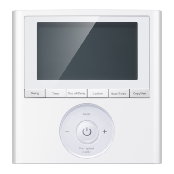
7. NAME OF THE BUTTONS ON THE WIRE CONTROLLER 1.-MODE button 6.-TIMER button 2.-POWER button 7.-DAY OFF / DELAY button 3.-ADJUST + and - button 8. -COPY / IFEEL button 4.-FAN SPEED button 9.-BACK / TURBO button 5.-SWING button 10.-CONFIRM button... -
Page 13: Preparatory Operation
8. PREPARATORY OPERATION Set the current day and time Press TIMER button for 3 seconds or more. Timer display will flash. Press button “+” or “-“ to set the date. The selected date will flash. When you press Timer button or not pressing any button in 10 seconds, you confirm date setting. -
Page 14: Operation
9. OPERATION To start/stop operation Press Power button. To set operation mode Operation mode setting Press Mode button to set operation mode. (Heat function is invalid for cool only type unit) Set point temperature setting Press button “+” or “-“to adjust setpoint temperature. Indoor Setting Temperature Range: 17~30ºC (62~86ºF/62~88ºF (Depending on models)). - Page 15 Child lock function Press Lock button for 3 seconds to activate the lock function and lock all buttons on the wire controller. Press the button again for 3 seconds to deactivate the lock function. When the lock function is active, the mark appears Keypad tone setting Press buttons Swing and Timer simultaneously for 3...
- Page 16 Swing function (For the unit left & right auto swing models only) Left-Right swing Press Swing button to start Left-Right swing function. Press it again to stop. When the Left-Right swing function is activated, the mark appears. Up-Down swing Press Swing button long to start Up-Down swing function. Press it again to stop.
- Page 17 Indoor unit Tx temperature query function When the air conditioning unit is switch machine, long press “COPY” for 3 seconds to enter query indoor unit Tn(T1~T4) temperature and fan Fault (CF), press“+”or “-”to select. Not operating keys 15 seconds or press “Back” press “ON/OFF”...
-
Page 18: Timer Functions
10. TIMER FUNCTIONS WEEKLY Timer Use this timer function to set operating times for each day of the week. ON Timer Use this timer function to start air conditioner operation. Air conditioner will start up when the configured time has passed. OFF Timer Use this timer function to stop air conditioner operation. -
Page 19: Weekly Timer
To set the ON and OFF TIMER Press Timer button to select the Press Confirm button and Clock display will flash. Press the button “+” or “-“to set the time of ON TIMER, and then press Confirm button to confirm setting. - Page 20 4.-OFF TIMER setting of timer setting 1 Press the button “+” or “-“ to set the time of OFF TIMER, and then press Confirm button to confirm the setting. ex.Tuesday time scale 1 5. - Different timer setting can be set by repeating step 3 to 4 6.
- Page 21 To set the DAY OFF (for a holiday) During the weekly timer, press Confirm button. Press the button “+” or “-“to select the day in this week. Press Day off button to set the DAY OFF. mark id hidden. Ex. The DAY OFF is set for Wednesday. The DAY OFF function can be used for other days by repeating the steps 2 and 3.
- Page 22 Copy settings of one day to another • Every timer program done once can be copied to other day of the week. Whole program of the selected day of the week can be copied. The effective use of the copy mode, is the easier way to make the weekly program.
-
Page 23: Setting Static Pressure For A6 Ducts
12. SETTING STATIC PRESSURE FOR A6 DUCTS 1.When the unit is in standby, press ‘copy’ button for 3s, the unit will enter into temperature query status, showing T1. 2.Press ‘+’ and ‘-’ button to select on-way resistance test item (shows AF), then press ‘confirm’... -
Page 24: Fault Alarm Handing
13. FAULT ALARM HANDING If the system does not properly operate, maybe any of alarm codes of the below table may appear in the LCD display of the wired controller. DISPLAY MALFUNCTION &PROTECTION DEFINE Communication error between wire controller and indoor unit The face plate is abnormal If the system continues still doesn't work well, please check the display in the indoor unit to see if an alarm code appears in it.
Need help?
Do you have a question about the KC-03.1 SPS and is the answer not in the manual?
Questions and answers