
Related Manuals for Kaysun KCCHT-05 MODBUS


Summary of Contents for Kaysun KCCHT-05 MODBUS
- Page 1 OWNER'S MANUAL KCCHT-05 MODBUS Thank you very much for purchasing our product. Before using your unit, please read this manual carefully and keep it for future reference.
- Page 3 ● This manual gives detailed description of the precautions that should be brought to your attention during operation. ● In order to ensure correct service of the wire controller, please read this manual carefully before using the unit. ● For convenience of future reference, keep this manual after reading it.
-
Page 4: Table Of Contents
Contents 1 Safety Precautions ............1 2 Overview of Wired Controller........3 3 Menu Operations ............5 4 Installation Manual...........25 5 Failure Information and Code ........37 6 Attached Table About Modbus ........41... -
Page 5: Safety Precautions
1 Safety Precautions The product and Operation and Installation Instructions record the following content, including the operation method, how to prevent harms to others and property losses, and how to use the product correctly and safely. Read the text after understanding the content (identification and marker maps) below carefully, and observe the precautions below. - Page 6 1 Safety Precautions Icon Name It indicates "prohibited". The specific content of prohibition is provided using graphics or text in the icon or nearby. It indicates "mandatory". The specific mandatory content is provided using graphics or text in the icon or nearby. Entrust your distributor or a professional to install the product.
-
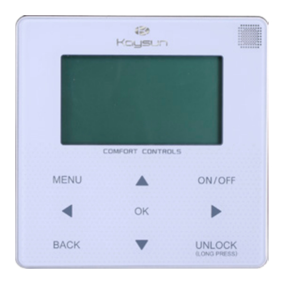
Page 7: Overview Of Wired Controller
2 Overview of Wired Controller Enter the menu ON/OFF MENU structure from Turn on or off the the home page space operation mode Navigate the cursor on the display/navigate in the menu MENU ON/OFF structure/ adjust the settings UNLOCK (LONG PRESS) Long press Come back to UNLOCK... - Page 8 2 Overview of Wired Controller 10:35 A 20/11/2017 Units Set temperature Tw operating ONLINE ON COOL Heating mode UNITES Cooling mode Number of parallel units Current temperature Tw ERROR Current ERROR Alarm Current temperature T5 Icon Timer WEEKLY TIMER ON TIMER ON WEEKLY icon...
-
Page 9: Menu Operations
3 Menu Operations 3.3 Setting Mode 3.1 Unlocking/Locking In Unlock mode, press the "MENU" button Operation to enter the menu setting interface, press the "▼" and "▲" buttons to select "MODE" When the wired controller is locked, press and and set a mode, and press the "OK" button hold the "UNLOCK"... - Page 10 When the current mode button is selected USER MENU (blinking), press "◄" and "►" to set a mode or temperature, and then press "▼" and TEMPERATURE COPENSATION TEMPERATURE COPENSATION "▲" to adjust the mode and set temperature value. After setting, press the "OK" button HEATER CONTROL(DISABLE) to save the setting and go back to the home HOT WATER SWITCH(DISABLE)
- Page 11 BACK ◆ State query: ◆ Setting the timer: Select "STATE QUERY" in the "QUERY" Select "TIMER" in the "USER MENU" interface, and press the "OK" button to interface, and press the "OK" button to enter the interface. The interface display is enter the interface.
- Page 12 When the cursor stays at "ACT", press the "ON/OFF" button to open or close daily timer function (default "OFF", indicating that the timer of this segment is invalid), and press the "◄" and "►" buttons to select the start time, end time, mode and temperature to be set, and then use the "▲"...
- Page 13 ◆ Setting the weekly schedule: When the cursor stays at "ACT", press the S elect "WEE K LY SC HED UL E" in t h e "ON/OFF" button to open or close daily timer "TIMER" interface, and press the "OK" function (default "OFF", indicating that the button to enter the interface.
- Page 14 Press the "▲" and "▼" buttons to select the Operation instructions: date and time to be set, and press the "OK" Press the "◄" and "►" buttons to select button to access the lower-layer submenu: "YEAT", "MONTH" and "DAY", press the "▲" and "▼"...
- Page 15 Press the "◄" and "►" buttons to adjust DOUBLE SETPOINT the parameter, and press the "OK" button to save the setting and return to the previous SETPOINT SETPOINT SETPOINT SETPOINT SETPOINT interface, or press the "BACK" button to COOL_1 COOL_1 HEAT_1 COOL_2 HEAT_2...
- Page 16 TEMP COMPENSATION-HEAT MODE SETPOINT OFFSET ENABLE HEAT_1 COOL_1 HEAT_2 25• • 25• • 25• • Press the "▲" and "▼" buttons to select the Operation instructions: COOL MODE and HEAT MODE, and press Press the "◄" and "►" buttons to select the the "OK"...
- Page 17 3.5 Setting PROJECT MENU PROJECT MENU SORRY, WRONY PASSWORD, ◆ Entering the password: PLEASE INPUT AGAIN. Select "PROJECT MENU", and press the "OK" button to enter the menu. The screen prompts the user to enter the password, as shown below: The query interface as follows is displayed if the input is correct: PROJECT MENU...
- Page 18 ◆ Set unit air-conditioning: Select "SET UNIT AIR-CONDITIONING", and press the "OK" button to enter the interface. The interface display is as follows: Tim_ Cap_Adj PROJECT MENU SELECT THE QUERING ADDRESS Tw_heat Tw_cool dT5_ON dT1S5 _Diff _Diff Press the "◄" and "►" buttons to select the desired option, and press "▲"...
- Page 19 Press the "▲" and "▼" buttons to set the ◆ Set heater: values and press "OK" button to save Select "SET HEATER", and press the "OK" the setting and return to the previous button to enter the interface, If it is controlled by single water pump.The interface display interface,or press the "BACK"...
- Page 20 HEAT2 function is disabled, so user can not enter the HEAT2 interface. ◆ Check parts Select "CHECK PARTS", and press the "OK" button to enter the interface. The interface display is as follows: Operation instructions: When select modbus "YES", and press "OK" button to access the function.User can use a host computer to communicate with the wired controller by modbus protocol,and...
- Page 21 The query interface as follows is displayed if the input is correct: SERVISE MENU STATE QUERY TEMPERATURE COPENSATION HISTORY ERROR QUERY The initial password is 9999 and cannot be changed. Press the "▲" and "▼" buttons to change the number to enter, and press the Press the "▼"...
- Page 22 Press the "▼" and "▲" buttons to select the address of module to view (the offline address is skipped automatically). Press the "OK" button to access the lower-layer submenu, or press "BACK" to go back to the previous interface. During operation on the menu page, press "BACK"...
- Page 23 Press the "◄" and "►" buttons to select the different page. ◆ History error query Press the "▼" and "▲" buttons to select "HISTORT ERROR QUERY" in the "SERVIE MENU" interface, and press the "OK" button to enter the interface. The interface display is as follows: HISTORY ERROR QUERY SELECT THE QUERING ADDRESS...
- Page 24 The wired controller can display 8 errors at QUERY most. Take the mainboard (00#) as an example to make further explanation of the submenu. SELECT THE QUERING ADDRESS After the mainboard is selected, the running state of mainboard is as shown below: HISTORY ERROR QUERY E2:COMMUNICATION ERROR Press the "▼"...
- Page 25 3.7 Setting Wired Controller Press the "▼" and "▲" buttons to select the desired option, If "YES" is selected Address then press the "OK" button to clear current address error, and return to the "HISTORY Press the "MENU" and "►" buttons for 3s ERROR QUERY"...
- Page 26 3.8 Power Failure Memory 4) Start point of data sharing: After the power-on/off button is pressed, data can Function be shared during parameter adjustment. The "OK" button must be pressed after The power supply to the system fails parameters are adjusted, and the finally unexpectedly during operation.
- Page 27 10:35 A MON 10:35A 20/11/2017 ONLINE COOL Tws SET ADDRESS UNITES ERROR WEEKLY TIMER ON TIMER ON The set address range is 0 to 15. When set address "01-15" and press "OK" button, the wired remote controller will enter Press the "▲" and "▼" buttons to select the the interface as follows: desired values.
- Page 28 3.11 Upper Computer Communication Function 1) The home page displays the content b e l o w d u r i n g c o m m u n i c a t i o n w i t h the upper computer: Communication between the wired controller and the upper computer.
-
Page 29: Installation Manual
4 INSTALLATION MANUAL 4.1 Safety precaution Read the safety precautions carefully before installing the unit. Stated below are important safety issues that must be obeyed. Conform there is no abnormal phenomena during test operation after complete, then hand the manual to the user. Meaning of marks: WARNING Means improper handling may lead to personal death or severe injury. - Page 30 CAUTION Do not install the unit in a place vulnerable to leakage of flammable gases. Once flammable gases are leaked and left around the wire controller, fire may occur. The wiring should adapt to the wire controller current. Otherwise, electric leakage or heating may occur and result in fire. The specified cables shall be applied in the wiring.
- Page 31 Name Qty. Remarks Wire controller Cross round head wood GB950-86 M4X20 mounting screw (For Mounting on the Wall) M4X25 GB823-88 (For Cross round head Mounting on the Electrical mounting screw Switch Box) Installation & Owner's Manual This accessory is used when Plastic bolt install the centralized control inside the electric cabinet...
- Page 32 4.2.3 Note to installation of wire controller: 1) This installation manual contains information about the procedure of installing Wired Remote Controller. Please refer to Indoor Unit Installation Manual for connecting between Wired Remote Controller and Indoor Unit. 2) Circuit of Wired Remote Controller is low voltage circuit. Never connect it with a standard 220V/380V circuit or put it into a same Wiring Tube with the circuit.
- Page 33 4.3.1 Structure size figure 20mm 120mm Figure A 46mm 60mm...
- Page 34 4.3.2 Wiring Main Unit control box X Y E A Communication with host computer, MODBUS protocol Wire controller Input Voltage (A/B) 10VAC Wiring size 0.75mm...
- Page 35 4.3.3 Back cover installation Buckling position Back cover Front cover Straight head screwdriver Screw hole installed on the wall,use three GB950-86 M4X20...
- Page 36 Screw hole fixed on the wall,use one GB950-86 M4X20 Screw hole installed on 86 Electrician box, use two M4X25 GB823-88 Back cover Signal switching wires...
- Page 37 4.3.4 Wire outlet 1) Use straight head screwdriver to insert into the buckling position in the bottom of wire controller, and spin the screwdriver to take down the back cover. (Pay attention to spinning direction, otherwise will damage the back cover!) 2) Use three GB950-86 M4X20 screws to directly install the back cover on the wall.
- Page 38 Wall hole and wiring hole Diameter: Φ8--Φ10 60mm Wiring hole Putty Avoid the water enter into Trap Putty Putty the wired remote controller, use trap and putty to seal the Trap connectors of wires during Trap wiring installation.
- Page 39 4.4 Front cover installation After adjusting the front cover and then buckle the front cover; avoid clamping the communication switching wire during installation. Sensor can not be affected with damp.
- Page 40 Correct install the back cover and firmly buckle the front cover and back cover, otherwise will make the front cover drop off.
-
Page 41: Failure Information And Code
5 Failure Information and Code Error code Content EEPROM error of main control board Power phase sequence error Communication error between main control board and wired controller Total water outlet temperature sensor error (master only) Outlet water temp sensor error 1E5 condenser tube temperature sensor T3A error 2E5 condenser tube temperature sensor T3B error Water tank temperature sensor T5 error... - Page 42 Error code Content Tz sensor error System high-pressure protection or discharge temperature protection System low pressure protection Tz total cold outlet temperature too high Reserved System A current protection System B current protection Module error High temperature protection of system condenser Reserved Water inlet and outlet temperature difference protection Reserved...
- Page 43 Error code Content Voltage too high or low No inset A valve error No inset B valve error No inset C valve error IPM module transmission error IPM module transmission error Superheat insufficient Fan A transmission error(reserved) Fan B transmission error(reserved) Fan C transmission error(reserved) PP protection occurs for 3 times in 60 minutes (power failure recovery) PP protection occurs for 3 times in 60 minutes (power failure recovery)
- Page 44 Error code Content DIP switch inconsistency of multiple water pumps 3 times PL module protection low-voltage protection high-voltage protection MCE error zero-speed protection phase loss frequency change over 15Hz frequency phase difference 15Hz Gate controlled switch protection (d0 and address display cyclically by 10 seconds) Defrosting prompt...
-
Page 45: Attached Table About Modbus
ATTACHED TABLE ABOUT MODBUS... - Page 46 6.1 Communication specification Interface: RS-485, H1 on the back of the controller, H2 connected to the serial port of T/R- and T/R+, H1, H2 as the RS485 differential signal. The Upper computer is the host, and the slave machine is the line controller the communication parameters are as follows: baud rate: 9600bps.
- Page 47 Exception code specification Exception MODBUS name Remarks code illegal function Function code not supported by line controller code illegal data The address sent in query or setting is undefined in the address line controller The set parameter is an illegal value, which exceeds the illegal data values reasonable set range...
- Page 48 6.3 Address mapping in register of wired controller Addresses below can be used as 03 (Read), 06 (Write in a single register), 16 (Write in several registers) Address of Data Notes Register 1: Cooling mode Modset 2: Heating mode 8: OFF Outlet water Cooling mode (0°C~20°C) temp.set (Tws)
- Page 49 The following address can use 03 (read) Address of Data Notes Register Compressor switch ON:1 OFF:0 status Fan switch status ON:1 OFF:0 Water pump switch ON:1 OFF:0 state Status of auxiliary heat ON:1 OFF:0 1 switch Status of auxiliary heat ON:1 OFF:0 2 switch...
- Page 50 The following address can use 03 (read) Address of Data Notes Register In water temp N*100+244 Units: °C Out water temp N*100+245 Units: °C Total outlet water N*100+246 Units: °C, only host 0 machine can read this parameter. temp. Ambient temp N*100+247 Units: °C Error or protect...
- Page 51 MD17IU-016AW(DZ) 16127100A04810...
Need help?
Do you have a question about the KCCHT-05 MODBUS and is the answer not in the manual?
Questions and answers